Advertisement
The side mounted SOR
for either a high or low level condition.
ow level condition.
The float moves a magnet into the field of a magnetically actuated pneumatic valve. The
pneumatic valve is pilot operated. An amplifying relay provides quick response.
The unit may be mounted for either high or low liquid level alarm by rotating the switch
body. Wrench flats provide ease of rotation.
High Level Pneumatic Output Signal (Direct Acting) Install with pneumatic connections
on the upper side of the body when the unit is tightened into the vessel.
Rising liquid level raises the float upward causing the float stem magnet to repel the
actuating lever magnet and seal the pilot nozzle. Resultant pilot pressure build-up triggers
the amplifying relay to pass pneumatic signal through the output port.
Low Level Pneumatic Output Signal (Reverse Acting) Install with pneumatic connections
on the lower side of the body when the unit is tightened into the vessel.
Falling liquid level lowers the float downward causing the float stem magnet to repel the
actuating lever magnet and seal the pilot nozzle. Resultant pilot pressure build-up
triggers the amplifying relay to pass pneumatic signal through the output port.
NOTE: If you suspect that a product is defective, contact the factory or the SOR Representative
in your area for a return authorization number (RMA). This product should only be installed by
trained and competent personnel.
Design and specifications are subject to change without notice.
Form 439 (04.13) ©SOR Inc.
®
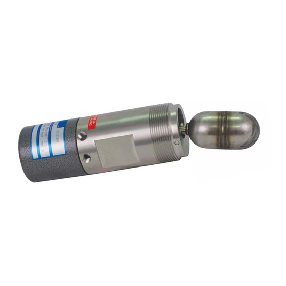
1530 Pneumatic Level Switch provides a pneumatic output signal
eumatic Level Switch provides a pneumatic output sig
For latest revision, go to www.sorinc.com
1530 Side Mounted
Pneumatic Level Switch
General Instructi
General Instructions
Registered Quality System to ISO 9001
el Sw
1/4
Advertisement
Table of Contents

Subscribe to Our Youtube Channel
Related Manuals for SOR 1530


Summary of Contents for SOR 1530
- Page 1 NOTE: If you suspect that a product is defective, contact the factory or the SOR Representative in your area for a return authorization number (RMA). This product should only be installed by trained and competent personnel.
- Page 2 APPLY TWO DROPS SET SCREW LOCTITE 271 INSIDE THREADED HOLE OF FLOAT FLOAT NOTE: Do not remove the set Linear = mm/inches screw as it secures the pivot arm to the shaft. Drawing 0390747 Form 439 (04.13) ©SOR Inc.
- Page 3 WRENCH PROCESS FLATS CONNECTION 50.8 2" NPTM 2.00 168.3 78.6 REF Linear = mm/inches 6.63 3.10 Drawing 0390026 1530 Operating Principle Schematic Actuating Lever Actuator Arm Pilot Nozzle Magnet Pilot Pressure Diaphragm Float Magnet Vent Restriction (0.015”) Output Restriction Filter Supply Form 439 (04.13) ©SOR Inc.
-
Page 4: Troubleshooting
Part Number Description 3130-052 316SS Float & Actuator Arm Assembly 3130-114 Pneumatic Relay Assembly sorinc.com 14685 West 105th Street, Lenexa, KS 66215 913-888-2630 800-676-6794 USA Fax 913-888-0767 Registered Quality System to ISO 9001 Form 439 (04.13) ©SOR Inc.
Need help?
Do you have a question about the 1530 and is the answer not in the manual?
Questions and answers