Advertisement
Available languages
Available languages
Quick Links
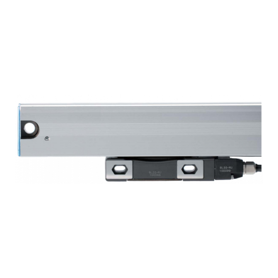
スケールユニット / Scale Unit / Maßstabseinheit
BL55-RU
お買い上げいただき、ありがとうございます。
ご使用の前に、この説明書を必ずお読みください。
ご使用に際しては、この説明書どおりお使いください。
お読みになった後は、後日お役に立つこともございますので、必ず保管してください。
Read all the instructions in the installation manual carefully before use and strictly follow
them.
Keep the manual for future references.
Lesen Sie die ganze Anleitung vor dem Betrieb aufmerksam durch und folgen Sie beim
Betrieb des Geräts den Anweisungen. Bewahren Sie diese Anbringungsanleitung zum
späferen Nachlesen griffbereit auf.
取付説明書 / Installation Manual / Anbringungsanleitung
Advertisement

Subscribe to Our Youtube Channel
Related Manuals for Magnescale LASERSCALE BL55-RU Series


Summary of Contents for Magnescale LASERSCALE BL55-RU Series
- Page 1 スケールユニット / Scale Unit / Maßstabseinheit BL55-RU お買い上げいただき、ありがとうございます。 ご使用の前に、この説明書を必ずお読みください。 ご使用に際しては、この説明書どおりお使いください。 お読みになった後は、後日お役に立つこともございますので、必ず保管してください。 Read all the instructions in the installation manual carefully before use and strictly follow them. Keep the manual for future references. Lesen Sie die ganze Anleitung vor dem Betrieb aufmerksam durch und folgen Sie beim Betrieb des Geräts den Anweisungen.
- Page 2 BL55-RU...
- Page 3 安全のために 警告 当社の製品は安全に充分配慮して設計されています。 · 表示された電源電圧以外での電圧で使 しかし、操作や設置時にまちがった取扱いをすると、 用しないでください。火災や感電の原 火災や感電などにより死亡や大ケガなど人身事故につ 因となる恐れがあります。 ながることがあり、危険です。また、機械の性能を落 · 濡れた手による取付作業はおやめくだ としてしまうこともあります。 さい。感電の原因となる恐れがありま これらの事故を未然に防ぐために、安全のための注意事 す。 項は必ず守ってください。操作や設置、保守、点検、修 理などを行う前に、この「安全のために」を必ずお読み · 本体を分解や改造しないでください。 ください。 ケガの恐れや、内部回路が破損するこ とがあります。 警告表示の意味 このマニュアルでは、次のような表示をしています。 · 本装置は、半導体レーザを使用したク 表示内容をよく理解してから本文をお読みください。 ラス1レーザ製品です。本装置に使用し ている半導体レーザの波長は可視帯域 警告 から外れた790 nm、最大出力は6 mW (クラス3B) です。 この表示の注意事項を守らないと、火災や感電などに より死亡や大ケガなど人身事故につながることがあり · ヘッド内部から照射されるレーザ光は ます。 目に見えませんが、人体に有害です。 スケールユニットを分解したり、ス ケールシール部から中を覗きこんだり...
- Page 4 日本工業規格 : JIS C6802 注意 レーザ製品の安全基準に適合しています。 · 作業を行なう前には、装置の状況をよ く確かめて作業の安全を確保してくだ クラス1レーザ製品 さい。 · 電源などの駆動源は必ず切って作業を してください。火災や事故の原因とな CDRH規定 ります。 米国食品医薬品局CDRH (Center for Devices and Radiological Health) のレーザ製品に関する規定 (1976年 · 電源などを入れて動かす場合は、周辺 8月1日施行) に適合しています。 機械や装置などに指を挟まれないよう 米国内で販売される製品はこの規準に適合する必要が に充分注意してください。 あります。 CLASS 1 LASER PRODUCT 国際規格 EN60825-1を含む該当する安全基準に適合していま す。 CLASS 1 LASER PRODUCT LASERSCHUTZKLASSE 1 PRODUKT TO EN 60825 BL55-RU...
- Page 5 使用上の注意事項 使用環境によるご注意 · インターフェイスユニットのコネクタプラグには静 、 の環境下でご使用になる場合、必ず下記対策を 電気保護用キャップが付いていますので、周辺機器 行なってください。 接続時まで取り外さないでください。 行なわない場合は、品質保証できません。 水溶性切削液を使用する場合 / 金属微粉末が発生 また、コネクタプラグの静電気保護キャップ取り外 する加工やセラミック、グラスファイバーなどの し後に、コネクタピンに触れないように特に注意し てください。故障の原因となります。 加工物を加工する場合 ホーミングマシンのような、長時間特定区間を高 · インターフェイスユニットのコネクタと周辺機器を 完全に接続してから電源スイッチをONにしてくだ 速摺動する機械に装着する場合 さい。 · 水溶性切削液や切屑が直接スケールにかからない場 また、電源をONしたままコネクタを抜き差ししな 所に取付けてください。 いでください。 · 内部に水溶性切削液のミストや粉塵が侵入しないよ · ケーブルを強く引いたり、無理に曲げてのご使用は うに、スケールカバーを取付けてください。 避けてください。{曲げ半径 (内側) 静止状態 : 30 mm · エアフィルタやミストセパレータなどを通したク 以上、可動状態 : 100 mm以上} リーンエアーを注入してください。 · 電源投入後10分位経過しますと、検出ヘッド部の温 度が安定状態となります。その後にご使用くださ 保存上のご注意...
- Page 6 [ For EU and EFTA countries ] [For U.S.A. and Canada] CE Notice THIS CLASS A DIGITAL DEVICE COMPLIES WITH Marking by the symbol CE indicates compliance with PART15 OF THE FCC RULES AND THE CANADIAN the EMC directive of the European Community. This ICES-003.
- Page 7 このたびは、当社の製品をお買い上げいただき、まことにありがとうございます。 ご使用方法は別売のBL55-RU取扱説明書をお読みください。 1. 機種構成 型名 有効長 中間フットの数 BL55-007RU ······ 70 mm BL55-012RU ······ 120 mm BL55-017RU ······ 170 mm BL55-022RU ······ 220 mm BL55-027RU ······ 270 mm BL55-032RU ······ 320 mm BL55-037RU ······ 370 mm BL55-042RU ······ 420 mm BL55-047RU ······ 470 mm BL55-052RU ······ 520 mm BL55-057RU ······ 570 mm BL55-062RU ······ 620 mm BL55-072RU ······ 720 mm BL55-077RU ······ 770 mm BL55-082RU ······ 820 mm BL55-087RU ······ 870 mm BL55-092RU ······ 920 mm BL55-102RU ······...
- Page 8 2. 取付に必要なもの 付属品 数量 六角穴付ボルト M8 × 25 スケール取付け用 六角穴付ボルト M4 × 25 スライダ取付け用 中間フット取付け用 (中間フットは有効長470 mm以下...0個、 520〜920 mm...1個、1020 mm...2個付いています。) 六角穴付ボルト M2.6 × 16 ヘッドケーブル固定用 六角ナット 呼び4 六角穴付ボルト M4 × 10 配線止め用 スプリングワッシャ 呼び4 スライダ取付け用 スプリングワッシャ 呼び4 中間フット取付け用 配線止め ヘッドケーブル固定用 スペーサ t = 0.05 スライダ取付け用 t = 0.1 スライダ取付け用 六角穴付ハーフユニオン 空気注入用 ワッシャ みがき丸呼び4 六角穴付ボルト M4 × 12 インターフェイスユニット用...
- Page 9 3. 取付面の加工寸法 · 図に指示するねじ (六角穴付ボルト) は、標準付属品とします。 · 有効長が520 mm 以上のスケールは、中間フットが必要です。 · 有効長を超えてスケールを動かすと破損します。機械可動長が有効長内に入るよう、充分注意してください。 BL55-RU...
- Page 10 4. スケールユニットとスライダの取付け 平行度0.05 mm/M (有効長120 mm以下) 平行度0.1 mm/M (有効長170 mm以上) M8 × 25 締付トルク22 N · m M4 × 25 締付トルク2.7 N · m M4 × 25 締付トルク2.7 N · m M8 × 25 締付トルク22 N · m ※ Mはマシンガイド (機械の走り) を示す。 単位 : mm · スケールユニットの両端および中間フットの付近で、図に示す平行度を出してください。 · スケール取付ねじは一度に締めず、仮締めし、平行度を出したあとに規定トルクで締めてくだ さい。 · 有効長520 mm以上のスケールの場合、中間フットも固定してください。 BL55-RU...
- Page 11 5. スライダの取付け確認 スケールユニットとスライダの隙間に、スライダ固定板のリブ部分がスムーズに入ることを確認 します。(スライダ固定板のリブ部分の厚み : 1 mm) スライダ固定板 リブ スライダ固定板が入らない場合もしくは大きくがたつく場合は、基準通りの取付けがされていま せんので、スケールとスライダの取付けを再度、最初から行なってください。 6. 空気注入について 空気注入口は、スケールユニット両端およびスライダの計3箇所にあります。 詳細は取扱説明書 (別売) をご確認ください。 ユニオン 適用チューブ外形 BL55-RU...
- Page 12 7. インターフェイスユニットの設定 出荷時状態 (出力形態 F, Hの場合) POS.ランプ 出荷時状態 MODEスイッチ (各種設定用) (出力形態 Gの場合) MODEスイッチ1 (原点POS 1 sw) MODEスイッチ2 (原点POS 2 sw) MODEスイッチ3 (Dir・sw) MODEスイッチ4 (常時OFF) MODEスイッチ5 (原点調整モードsw) MODEスイッチ6 (分解能設定sw) MODEスイッチ7 (常時OFF) MODEスイッチ8 (アラームモードsw) MODEスイッチ9 (常時OFF) MODEスイッチ10 (原点モードsw) MODEスイッチ A / B相出力タイプ アナログ出力タイプ 1, 2 POS. ランプ点灯 MODEスイッチ1 MODEスイッチ2 MODEスイッチ1 ..
- Page 13 8. 入出力コネクタ 8-1. コネクタ インターフェイスユニット側 : R04-R12M (多治見無線電機 (株) 製) ケーブル側 : R04-P12F (多治見無線電機 (株) 製) ..... 防水タイプ : R03-PB12F (多治見無線電機 (株) 製) ..非防水タイプ ピン記号 入出力仕様 A / B相出力 アナログ出力 +COS ∗ A −COS +SIN ∗ B −SIN C D E +REF ∗ Z −REF +5 V (電源) 0 V (電源) 0 V (信号) 0 V (信号) +5 V S 0 V S 注意 · 0 Vは回路GNDであり、フレームGNDとは接続されていません。 ·...
- Page 14 BL55-RU...
-
Page 15: Safety Precautions
Safety Precautions Warning Magnescale Co., Ltd. products are designed in full • Do not use this unit with voltages other consideration of safety. However, improper handling than the specified supply voltages as this during operation or installation is dangerous and may may result in fire or electric shock. - Page 16 See Manual DHHS label CERTIFICATION PRODUCT COMPLIES WITH DHHS RULES 21 CFR SUBCHAPTER J APPLICABLE AT DATE OF MANUFACTURE. Magnescale Co., Ltd. Shinagawa Intercity Tower A-18F, 2-15-1, Konan, Minato-ku, Tokyo 108-6018, Japan MANUFACTURED AT ISEHARA PLANT Magnescale Co., Ltd. ∗∗...
- Page 17 General Precautions the scale unit to prevent noise and electromagnetic in- terference from other equipment. When using Magnescale Co., Ltd. products, observe • Do not pass the head cable and connection cable the following general precautions along with those given through the same duct as the power line.
- Page 18 [ For EU and EFTA countries ] [For U.S.A. and Canada] CE Notice THIS CLASS A DIGITAL DEVICE COMPLIES WITH Marking by the symbol CE indicates compliance with PART15 OF THE FCC RULES AND THE CANADIAN the EMC directive of the European Community. This ICES-003.
-
Page 19: Series Models
Thank you for purchasing this Magnescale Co., Ltd. product. For the operating procedures, refer to the BL55-RU Instruction Manual (sold separately). 1. Series Models Model name Measuring length Number of foot plates BL55-007RU ······· 70 mm BL55-012RU ······· 120 mm BL55-017RU ·······... -
Page 20: Items Required For Installation
2. Items Required for Installation Accessories Quantity M8 × 25 Hex. socket-head cap screw For Scale installation M4 × 25 Hex. socket-head cap screw For Slider installation For foot plate installation (Measuring length of 470 mm or less: No foot plate; measuring length of 520 mm to 920 mm: 1 foot plate;... - Page 21 3. Machining Dimensions of Mounting Surface • The screws (hex. socket-head cap screws) shown in the figure are supplied as standard. • Scales having an effective length of 520 mm (20.472") or more require a foot plate. • The scale will be damaged if it moved past the effective length. Be extremely careful that the machine movable length fits within the measuring length.
- Page 22 4. Installation of Scale Unit and Slider Parallelism 0.05 mm/M (Measuring length of 120 mm (4.724") or less) 25 (0.984") Parallelism 0.1 mm/M 10 (0.394") (Measuring length of 170 mm (6.693") or more) 20 (0.784") 10 (0.394") 10 (0.394") × 25 (0.984") Tightening torque 22 N ·...
-
Page 23: Air Injection
5. Slider Installation Check Check that the rib section of the slider holding plate fits smoothly into the space between the scale unit and slider. (Thickness of the rib section of the slider holding plate: 1 mm (0.039")) Slider holding plate The scale and slider were not attached properly if the slider holding plate does not fit or rattles noticeably. - Page 24 7. Interface Unit Settings Default setting status POS. lamp (In the case of output format F, H) MODE switches (for various settings) Default setting status (In the case of output format G) MODE switch 1 (Reference point POS1 switch) MODE switch 2 (Reference point POS2 switch) MODE switch 3 (Direction switch)
-
Page 25: Input/Output Connectors
8. Input/Output Connectors 8-1. Connectors Interface unit side : R04-R12M (manufactured by TAJIMI ELECTRONICS CO., LTD.) Cable side : R04-P12F (manufactured by TAJIMI ELECTRONICS CO., LTD.) ..Waterproof type : R03-PB12F (manufactured by TAJIMI ELECTRONICS CO., LTD.) ..Non-waterproof type Pin arrangement Input/output specifications A/B signal output... - Page 26 BL55-RU...
- Page 27 Sicherheitsmaßnahmen Warnung Bei dem Entwurf von Magnescale Co., Ltd. Produkten • Betreiben Sie dieses Gerät nur mit der wird größter Wer t auf die Sicherheit gelegt. vorgeschriebenen Versorgungsspannung, Unsachgemäße Handhabung während des Betriebs da anderenfalls die Gefahr von Feuer oder oder der Installation ist jedoch gefahrlich und kann zu elektrischen Schlägen besteht.
- Page 28 See Manual DHHS-Etikett CERTIFICATION PRODUCT COMPLIES WITH DHHS RULES 21 CFR SUBCHAPTER J APPLICABLE AT DATE OF MANUFACTURE. Magnescale Co., Ltd. Shinagawa Intercity Tower A-18F, 2-15-1, Konan, Minato-ku, Tokyo 108-6018, Japan MANUFACTURED AT ISEHARA PLANT Magnescale Co., Ltd. ∗∗ 2-933-725-...
- Page 29 Vorsichtsmaßregeln zum Betrieb Hinweise zur Betriebsumgebung • Der Stecker der Schnittstelleneinheit ist mit einer Wenn Sie die Maßstabseinheit in den unten Kappe zum Schutz gegen statische Elektrizität beschriebenen Umgebungen oder benutzen, versehen. Entfernen Sie diese Kappe erst unmittelbar sollten immer folgenden vor dem Anschluß...
- Page 30 [ For EU and EFTA countries ] [For U.S.A. and Canada] CE Notice THIS CLASS A DIGITAL DEVICE COMPLIES WITH Marking by the symbol CE indicates compliance with PART15 OF THE FCC RULES AND THE CANADIAN the EMC directive of the European Community. This ICES-003.
- Page 31 Wir danken Ihnen für den Kauf dieses Produkts von Magnescale Co., Ltd. Einzelheiten zu den Bedienungsverfahren entnehmen Sie bitte der Bedienungsanleitung des Modells BL55- RU (getrennt erhältlich). 1. Modellkonfiguration Modell Messlänge Anzahl der Fußplatten BL55-007RU ······· 70 mm BL55-012RU ·······...
- Page 32 2. Für die Montage erforderliche Teile Zubehör Menge M8 × 25 Innensechskantschraube Zur Befestigung des Maßstabs M4 × 25 Innensechskantschraube Zur Befestigung des Schiebers Zur Befestigung der Fußplatten (Messlänge von maximal 470 mm: keine Fußplatte; Messlänge von 520 mm bis 920 mm: 1 Fußplatte; Messlänge von 1020 mm: 2 Fußplatten) M2,6 ×...
- Page 33 3. Bearbeitungsmaße der Montagefläche • Die in der Abbildung gezeigten Schrauben (Innensechskant-Zylinderkopfschrauben) werden als Standardzubehör mitgeliefert. • Für Maßstäbe mit einer Messlänge von 520 mm oder mehr ist eine Fußplatte erforderlich. • Der Maßstab wird beschädigt, falls er über die Messlänge hinaus bewegt wird. Achten Sie mit größter Sorgfalt darauf, dass die Bewegungslänge der Maschine innerhalb der Messlänge liegt.
- Page 34 4. Montage von Maßstabseinheit und Schieber Parallelität 0,05 mm/M (Messlänge von maximal 120 mm) Parallelität 0,1 mm/M (Messlänge von 170 mm oder mehr) × Anzugsmoment 22 N · m × Anzugsmoment 2,7 N · m × Anzugsmoment 2,7 N · m ×...
- Page 35 5. Prüfung der Schiebermontage Prüfen Sie, ob der Rippenteil der Schieberhalteplatte einwandfrei in den Spalt zwischen Maßstabseinheit und Schieber passt. (Dicke des Rippenteils der Schieberhalteplatte: 1 mm) Schieberhalteplatte Rippe Maßstab und Schieber sind nicht richtig montiert, wenn die Schieberhalteplatte nicht passt oder merklich klappert.
- Page 36 7. Einstellungen der Schnittstelleneinheit Standardeinstellungszustand POS-Lampe (Im Falle der Ausgabeform F, H) MODE-Schalter (für verschiedene Einstellungen) Standardeinstellungszustand (Im Falle der Ausgabeform G) MODE-Schalter 1 (Bezugspunktschalter POS1) MODE-Schalter 2 (Bezugspunktschalter POS2) MODE-Schalter 3 (Richtungsschalter) MODE-Schalter 4 (immer OFF) MODE-Schalter 5 (Bezugspunkt-Einstellungsmodusschalter) MODE-Schalter 6 (Teilungszahl-Einstellschalter) MODE-Schalter 7...
- Page 37 8. Ein-/Ausgangsanschluss 8-1. Anschluss Schnittstelleneinheitsseite : R04-R12M (hergestellt von der Firma TAJIMI ELECTRONICS CO., LTD.) Kabelseite : R04-P12F (hergestellt von der Firma TAJIMI ELECTRONICS CO., LTD.) ... Wasserdichter Typ : R03-PB12F (hergestellt von der Firma TAJIMI ELECTRONICS CO., LTD.) ..Nicht-wasserdichter Typ Stiftanordnung Ein-/Ausgangsspezifikationen A/B-Signalenausgang...
- Page 38 BL55-RU...
- Page 39 保 証 書 保証規定 フリガナ お 名 様 お z 保証の範囲 前 客 q 取扱説明書、本体添付ラベル等の注意書に従った正 〒 電話 - - ご 常な使用状態で、保証期間内に故障した場合は、無 様 住 償修理いたします。 所 w 本書に基づく保証は、本商品の修理に限定するもの とし、それ以外についての保証はいたしかねます。 お買上げ日 年 月 日 保 期 x 保証期間内でも、次の場合は有償修理となります。 証 間 本 体 1 年 q 火災、地震、水害、落雷およびその他天災地変によ る故障。 型 BL55-RU w 使用上の誤りおよび不当な修理や改造による故障。 名...
- Page 40 〒 108-6018 東京都港区港南2丁目 15番1号 品川インターシティA棟18階 Shinagawa Intercity Tower A-18F, 2-15-1, Konan, Minato-ku, Tokyo 108-6018, Japan BL55-RU 2010.4 2-918-395-04 Printed in Japan ©2002 Magnescale Co., Ltd. このマニュアルは再生紙を使用しています。...
Need help?
Do you have a question about the LASERSCALE BL55-RU Series and is the answer not in the manual?
Questions and answers