
Related Manuals for MSA Ultra Elite Responder


Summary of Contents for MSA Ultra Elite Responder
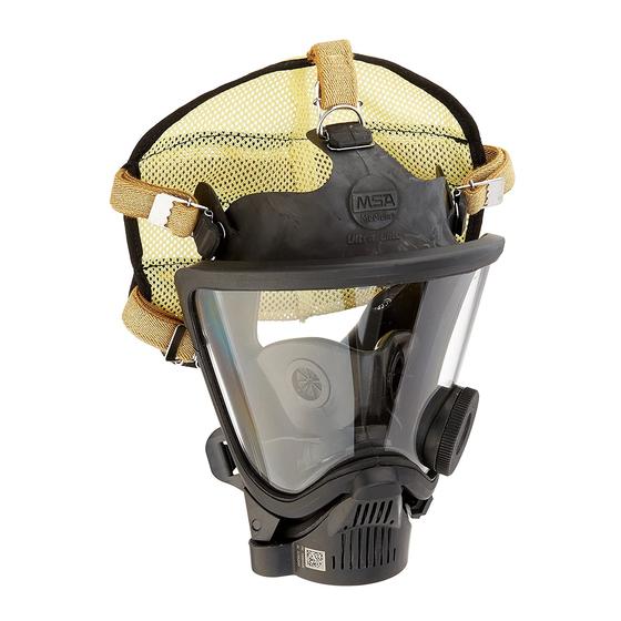
- Page 1 Ultra Elite ® Responder ® Facepiece MAINTENANCE AND REPAIR TAL 012 (L) Rev. 1 © MSA 2010 Prnt. Spec. 10000005389(I) Mat. 10096395 Doc. 10096395...
- Page 2 ULTRA ELITE RESPONDER FACEPIECE Replacement Kits Parts List Item Description Description Ultra Elite Responder Facepiece 10093924 Small 10093933 Lens Assembly 10093923 Medium 10025295 Lens Receptacle Inhalation Valve Disc 10093925 Large 10082477 O-Ring 10093027 Small, CC-ready* 10093919 Lens Port Plug 10093026...
- Page 3 ULTRA ELITE RESPONDER FACEPIECE Exploded View Christo-Lube Christo-Lube TAL 012 (L) Rev. 1 - 10096395...
-
Page 4: Table Of Contents
ULTRA ELITE RESPONDER FACEPIECE Table of Contents Disassembly ..............4 Speaking Diaphragm ............10 SpeeD-ON ® Head Harness ..........4 Component Housing Cover (Assembly) ......10 M7 HUD Mounting Bracket .........4 Pneumatic Assembly............10 Pneumatic Piston ............11 Lens Ring and Lens Assembly ........5 Nosecup...............5 Component Housing............12 Component Housing Cover (Removal) ......5... -
Page 5: Lens Ring And Lens Assembly
ULTRA ELITE RESPONDER FACEPIECE 3. Carefully pry the tab 3. Pull the lens off of the boss. out of the groove. Removing the Nosecup 4. Slide the bracket off of the facepiece. 1. Carefully pull the nosecup from the retaining ring. -
Page 6: Exhalation Valve
ULTRA ELITE RESPONDER FACEPIECE Removing the Component Housing 1. Remove the component housing cover. (See Removing the Component Housing Cover for 3. Use a Phillips instructions.) screwdriver to remove the two component housing cover screws. 2. Use a Phillips screwdriver to remove the component housing ring screw. -
Page 7: Pneumatic Assembly
ULTRA ELITE RESPONDER FACEPIECE Removing the Pneumatic Assembly b. Lift the pneumatic retainer out of the component housing cover. 1. Remove the pneumatic tube. c. Remove the pneumatic spring. a. Use retaining ring pliers to remove the retaining ring. d. Gently remove the exhalation valve spring. -
Page 8: Component Housing
ULTRA ELITE RESPONDER FACEPIECE Removing the External and Internal Drinking Tubes d. Use the o-ring removal tool to remove the o-ring. 1. Pull the external drinking tube off of the connector. e. Discard the o-ring. Disassembling the Component Housing Removing the Speaking Diaphragm 2. -
Page 9: Inlet Gasket And Disc Valve
ULTRA ELITE RESPONDER FACEPIECE Removing the Inlet Gasket and Disc Valve Note: Alignment of the tabbed spoke with the centerline provides a visual guide when installing the drinking tube assembly 1. Remove the spider and is not critical to gasket. -
Page 10: Internal And External Drinking Tube
ULTRA ELITE RESPONDER FACEPIECE Installing the Internal and External Drinking Tube Installing the Speaking Diaphragm External Drinking Tube P/N 10093935 Speaking Diaphragm P/N 804809 Internal Drinking Tube P/N 10093937 Retaining Ring P/N 804808 Drinking Tube Connector P/N 10082503 1. With the gasket 1. -
Page 11: Pneumatic Piston
ULTRA ELITE RESPONDER FACEPIECE a. Use the retaining ring pliers to install a d. Install the o-ring. new retaining ring. 2. Install the nut. e. Install the pneumatic nut. Use the inch pound torque wrench, ¼” socket, and Pneumatic Nut Special Tool (P/N 10086032) and tighten to 8 in lbs. -
Page 12: Component Housing
ULTRA ELITE RESPONDER FACEPIECE Installing the Component Housing Catch 1. Slide the housing into the front of the facepiece. a. Starting at the top (narrow end) of the housing, 2. Assemble the work the housing into the groove. exhalation spring onto the piston. -
Page 13: Exhalation Valve
ULTRA ELITE RESPONDER FACEPIECE 5. Moisten the mating surfaces of the facepiece and housing ring with Snoop (P/N 600920). If facepiece rubber extrudes between the component 6. Check by gently squeezing the ring ends together. housing ring ends, loosen the ring, adjust, and Bulges or wrinkles indicate that the rubber is not reassemble. -
Page 14: Nosecup
ULTRA ELITE RESPONDER FACEPIECE Installing the Nosecup 1. Install the nosecup. a. Install Phillips screws and tighten. a. Pass the drink tube through the x- ut in he nosecup. 4. Install the drinking tube coupling. a. Lubricate the barb with Snoop (P/N 600920). -
Page 15: Lens Assembly And Lens Ring
ULTRA ELITE RESPONDER FACEPIECE Installing the Lens Assembly and Lens Ring Lens Assembly P/N 10093933 Lower Lens Ring: P/N 804805 5. Work the groove Upper Lens Ring: P/N 804804 around the lens to seat the lens. 1. Remove dirt, lens fragments, or debris from the groove. -
Page 16: M7 Hud Mounting Bracket
ULTRA ELITE RESPONDER FACEPIECE a. Make sure that tab 8. Install the lens ring. is under the lower lens ring. 9. Press the ring halves together to mate the 2. Reinstall the lens ring ends. screw. 10. Install a screw on each side. -
Page 17: Lens Receptacle O-Ring
ULTRA ELITE RESPONDER FACEPIECE Lens Receptacle Inhalation Valve Removing the Lens Receptacle Inhalation Valve 1. Stretch the inhalation valve disc off the post. 2. Pull the entire lug through. Note: Lens assembly removed for illustration purposes only. It is not... -
Page 18: Ommunication System
ULTRA ELITE RESPONDER FACEPIECE ClearCommand Communication System Note: If upgrading from a speaking diaphragm to the 5. Use a small Phillips ClearCommand Communication System, remove the speaking diaphragm. (See Removing the Speaking screwdriver to Diaphragm for instructions.) disconnect the ClearCommand... -
Page 19: Clearcommand Microphone
ULTRA ELITE RESPONDER FACEPIECE Installing the ClearCommand Microphone ClearCommand Microphone P/N 10024076 Retaining Ring P/N 10023505 b. Stretch the nose cup over the retaining ring. 1. Thread the cable through the component housing. 6. Route the microphone cable over the 2. -
Page 20: Clearcommand Communication System Mounting Bracket
ULTRA ELITE RESPONDER FACEPIECE Installing the ClearCommand Communication System Cleaning and Disinfecting Mounting Bracket ClearCommand Communication System In general, only the facepiece requires cleaning and Mounting Bracket P/N 10024077 disinfecting after each use. Cleaning the SpeeD-ON Head Harness 1. Remove the component housing cover. (See Removing the Component Housing Cover for instructions.)
Need help?
Do you have a question about the Ultra Elite Responder and is the answer not in the manual?
Questions and answers