Table of Contents
Advertisement
Quick Links
Download this manual
See also:
User Manual
Advertisement
Table of Contents

Related Manuals for DeDietrich KALIKO TWH 200 EV


Summary of Contents for DeDietrich KALIKO TWH 200 EV
- Page 1 EASYLIFE KALIKO Installation and Service Manual Thermodynamic water heater KALIKO TWH 200 EV S U S T A I N A B L E C O M F O R T ®...
-
Page 2: Table Of Contents
Contents Contents Safety ................... . 5 Safety . - Page 3 Contents 5.9.1 Radio connection (installation strongly recommended) ......... 34 5.9.2 Wire connection .
- Page 4 Contents 10.2 Spare parts ................. . 70 10.2.1 Heat pump .
-
Page 5: Safety
1 Safety Safety Safety Danger This appliance can be used by children aged from 8 years and above and persons with reduced physical, sensory or mental capabilities or lack of experience and knowledge if they have been given supervision or instruction concerning use of the appliance in a safe way and understand the hazards involved. -
Page 6: Electrical Connections
1 Safety Connect the pressure limiter device to a drain pipe, kept open to the air, in a frost-free environment, and at a continuous downward gradient. 1.1.3 Electrical connections A disconnection device must be fitted to the permanent pipes in accordance with installation rules. If the power cable is damaged, it must be replaced by the manufacturer, its after sales service or persons with similar qualifications in order to obviate any... -
Page 7: Others
1 Safety 1.1.5 Others Danger If flue gas is released or there is a refrigerant leak: Do not use a naked flame, do not smoke, do not operate electrical contacts or switches (doorbell, light, motor, lift, etc.). Open the windows. Switch off the appliance. -
Page 8: Installer's Liability
1 Safety Our liability as manufacturer may not be invoked in the following cases: Failure to abide by the instructions on installing and maintaining the appliance. Failure to abide by the instructions on using the appliance. Faulty or insufficient maintenance of the appliance. 1.3.2 Installer's liability The installer is responsible for the installation and initial... -
Page 9: Composition Of/Information On The Ingredients
1 Safety Caution If the refrigerant is mixed with air, it may cause pressure surges in the refrigeration pipes and lead to an explosion and other hazards. 1.4.3 Composition of/Information on the ingredients Chemical nature: R-134a 1,1,1,2-Tetrafluoroethane. Ingredients that may lead to hazardous situations: Tab.1 Substance Concentration CAS number... -
Page 10: In The Event Of Accidental Spillage
1 Safety Effect of heat: release of toxic and corrosive vapours. Special intervention methods: Cool the volumes exposed to heat with water spray. Protection of the firemen: Full self-contained breathing apparatus. Complete body protection. 1.4.6 In the event of accidental spillage Individual precautions: Avoid contact with the skin and eyes. -
Page 11: Considerations On Disposal
1 Safety Do not drink, eat or smoke in the work place. 1.4.9 Considerations on disposal Product waste: Consult the manufacturer or the supplier for information on recovery or recycling. Soiled packaging: Reuse or recycle after decontamination. Destroy in authorised installations. Warning Disposal must be completed in compliance with prevailing local and national regulations. -
Page 12: About This Manual
2 About this manual About this manual Symbols used in the manual This manual uses various danger levels to draw attention to special instructions. We do this to improve user safety, to prevent problems and to guarantee correct operation of the appliance. Danger Risk of dangerous situations that may result in serious personal injury. -
Page 13: Technical Specifications
3 Technical specifications Technical specifications Homologations 3.1.1 Certifications CSTBat certification This product: complies with Technical Specification 14.5/17–2285_V1 and its commercial extension 14.5/17–2285_V1–E1. is CSTBat Humidity-Controlled Ventilation certified (www.certita.fr): CSTBat–71/01–CHY5–2285 NF certification Specifications LCIE 103-15/B 07/2011 for NF Electricity Performance Marking This product complies with the requirements of the following NF Electricity Standards: EN 60335-1:2002 +A1:2004 +A11:2004 +A12:2006 +A2:2006... - Page 14 3 Technical specifications Maximum domestic hot water temperature without electrical back-up °C Maximum domestic hot water temperature with electrical back-up °C Vmax (Maximum usable volume of hot water) 303.1 Modulating air flow rate (Maximum) Modulating air flow rate (Minimum) Available air pressure 100 or 125 Sound output dB(A)
-
Page 15: Description Of The Product
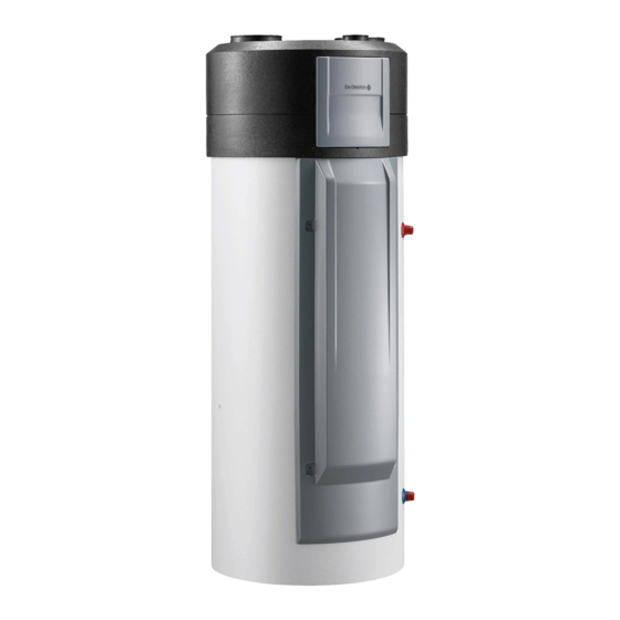
4 Description of the product Description of the product General description The TWH 200 EV water heater has the following specifications: Floor-standing thermodynamic storage water heater Thermodynamic unit extracting energy from the air Remote control panel (wireless) with display of the volume of heated water and timer programming Steatite immersion heater (2.4 kW) Enamelled tank, protected by impressed current anode... -
Page 16: Main Components
4 Description of the product Main components Fig.1 1 Air discharge connection, Ø160 2 Filter access hatch 3 Cover 4 Fan 5 Evaporator 6 Expansion valve 7 Control system 8 Control module 9 Housing for temperature sensor 10 Impressed current anode 11 Safety thermostat 12 Steatite immersion heater 13 Housing for temperature sensor... -
Page 17: Linear Network
4 Description of the product 4.3.1 Linear network Linear network with a maximum of four sanitary extractor fan outlets In this configuration, the air duct vacuum pressure set point (parameter ) must be set to 1 (= 100 Pa). Fig.2 1 Sanitary extractor fan outlets, Ø... -
Page 18: Direct Connection To The Thermodynamic Water Heater
4 Description of the product Important This configuration may include a maximum of: 3 bathrooms 3 WCs 1 kitchen 4.3.2 Direct connection to the thermodynamic water heater In this configuration, the air duct vacuum pressure set point (parameter ) must be set to 1 (= 100 Pa). Fig.4 1 Sanitary extractor fan outlets, Ø... -
Page 19: Schematic Diagram
4 Description of the product Fig.5 1 Sanitary extractor fan outlets, Ø 80 mm (bathroom/WC) 2 Kitchen extractor fan outlet, Ø 125 mm Ø80 3 Thermodynamic water heater 4 Duct (insulated if outside of the heated area) 5 Wall-mounted discharge 6 Collector 7 160 Tee fitting + 160/125 reduction sleeve Ø125... -
Page 20: Installation
5 Installation Installation Installation regulations Caution The appliance must be installed and maintained by a certified professional in accordance with prevailing statutory texts and codes of practice. Caution Install the thermodynamic water heater in a dry, frost-free location which is within the thermal envelope of the home. Caution Attach the CMV network ducts to the water heater using adhesive tape or a clamp, ensuring compliance with the requirements of... -
Page 21: System Configuration
5 Installation Accessories Package Roof cowl, Ø 160 (tile colour) EH309 Roof cowl, Ø 160 (slate colour) EH370 Wall duct with grille, Ø 160 EH208 External grille, Ø 160 (aluminium) EH209 Flexible insulated duct, Ø 80 (insulation thickness 50 mm and length 6 m) EH312 Flexible insulated duct, Ø... - Page 22 5 Installation Basic configuration Additional technical components Type Humid Air inlet module Extractor fans: flow rate (m /h) / package no. rooms Living Kitchen Bath BthRm / Bath Other Other Other Wash home room bed room room / bath bath room Flow room...
- Page 23 5 Installation Basic configuration Additional technical components Type Humid Air inlet module Extractor fans: flow rate (m /h) / package no. rooms Living Kitchen Bath BthRm / Bath Other Other Other Wash home room bed room room / bath bath room Flow room...
- Page 24 5 Installation Basic configuration Additional technical components Type Humid Air inlet module Extractor fans: flow rate (m /h) / package no. rooms Living Kitchen Bath BthRm / Bath Other Other Other Wash home room bed room room / bath bath room Flow room...
-
Page 25: Storing And Transporting The Appliance
5 Installation Storing and transporting the appliance Caution Have 2 people available. Use a 3-wheel hand truck. Handle the appliance with gloves. The appliance cover cannot be used for transport operations. The cover is not capable of withstanding heavy weights. Ensure the room height is a minimum of approximately 2.10 m. -
Page 26: Choice Of The Location
5 Installation Fig.7 Caution It is prohibited to stack or set down the appliance any of its other sides, as this may lead to malfunctions or faults. MW-1000371-1 Choice of the location 5.4.1 Data plate Fig.8 The data plate must be accessible at all times. The data plate identifies the product and provides the following information: Appliance type... - Page 27 5 Installation Recommended positions Fig.9 Install the appliance in a dry, frost-free room at a minimum temperature of 7 °C (optimum temperature: 20 °C). 6 5 0 Install the appliance on a flat, solid surface. Install the appliance on a base frame. The base frame must be able to support the load sufficiently at all times.
-
Page 28: Main Dimensions
5 Installation 5.4.3 Main dimensions Fig.12 o 632 M002832-E 50° 133° 1 Domestic hot water outlet G 3/4" – Dielectric union 3 Condensates outlet fitted (1) Adjustable feet 2 Domestic cold water inlet G 3/4" For more information, see Positioning the appliance, page 29 TWH 200 EV EN-7602142 - v11 - 24042019... -
Page 29: Positioning The Appliance
5 Installation Positioning the appliance 5.5.1 Unpacking the appliance Caution Remove all packaging materials. Check that the contents are intact. If you notice a defect, do not use the appliance and contact the supplier. Fig.13 1. Remove the 3 retaining screws. 2. - Page 30 5 Installation Fig.14 3. Undo the 3 nuts placed on top of the compressor retaining components and discard. 4. Remove the compressor retaining components and discard. M002965-B Fig.15 5. Remove the control system display from its transport housing. 6. Refit the cover. Warning Check that no foreign bodies have made their way inside the cover.
-
Page 31: Positioning The Appliance
5 Installation 5.5.2 Positioning the appliance Instructions affixed to the appliance packaging Caution After positioning the appliance, wait 3 hours before commissioning. 5.5.3 Levelling the appliance 1. Level the appliance using the adjustable feet. Fig.16 (1) Adjustable feet Basic dimension: 4 mm Possible adjustment: from 4 mm to 21 mm M002833-C Water connections... - Page 32 5 Installation Specific precautions Caution Do not connect the domestic hot water connection directly to copper pipes in order to prevent galvanic couplings in iron/copper (risk of corrosion). It is compulsory to fit the domestic hot water connection with a dielectric union (provided).
-
Page 33: Fitting The Dielectric Union
5 Installation 5.6.2 Fitting the dielectric union Important The dielectric union and its gasket are provided in the documentation bag. Fig.17 1. Screw the dielectric union onto the domestic hot water outlet, inserting the gasket. C004590-C Air duct connections Fig.18 1. -
Page 34: Condensate Discharge
5 Installation Condensate discharge Fig.19 1. Fit a siphon into the condensate discharge duct. Caution If no siphon is fitted, there is a risk of problems with the discharge of condensates when the compressor is running. 2. Attach the run-off collector. min. - Page 35 5 Installation Fig.20 C004121-D 1. Drill 2 holes 6 mm in diameter. 2. Put the plugs in place. 3. Attached the wall bracket (washers + screws provided). Important The screws and plugs are supplied in the bag of hardware. 4. Remove the protective cover from the battery compartment (batteries provided) at the back of the control module.
-
Page 36: Wire Connection
5 Installation 5.9.2 Wire connection Fig.21 C004124-D 1. Drill 2 holes 6 mm in diameter. 2. Put the plugs in place. 3. Attached the wall bracket (washers + screws provided). Important The screws and plugs are supplied in the bag of hardware. 4. -
Page 37: Integration Into The Front Panel Of The Water Heater (Optional)
5 Installation 9. Connect the wire to the back of the control module then clip the control module into its bracket. Important Remove the batteries from the control module. Fig.22 A Control module B Water heater PCB Important Type of cable: H05VV-F 2x1.0 mm (for example) C004125-C 5.9.3... -
Page 38: Electrical Connections
5 Installation 4. Fit the control module onto the front panel supplied in the option package (washers + screws provided). Important The screws and washers are supplied in the EH290 accessories package. 5. Connect the 2 wires on the control panel side. 6. -
Page 39: Connection With Peak Rate/Off-Peak Rate Signal Connected
5 Installation Fig.24 2. Connect the electrical connection using a cable with a cross section of 1.5 mm For more information, see Fitting and connecting the control module, page 34 HC/HP 5.10.3 Connection with peak rate/off-peak rate signal connected Connection with HP/HC relay via a shunt Fig.25 538 kW/h 15 / 45 A... - Page 40 5 Installation The heat pump and the back-up are not authorised to operate at peak rate. Boost one-touch quick heating. The 2 wires for the HP/HC signal must be connected to the terminal block X11 on the water heater PCB. For more information, see List of parameters, page 52 Connection with direct peak rate/off-peak rate contact on the...
-
Page 41: Connection With Timer Programming
5 Installation 5.10.4 Connection with timer programming Fig.27 538 kW/h 15 / 45 A 500 mA C1 C2 40 A 16 A TEST M002837-C 1 Counter 3 AC-type/30 mA differential switch 2 Connection circuit breaker 4 Circuit breaker Easy to install. Opt for timer programming to benefit from the peak rate/off-peak rate tariff. -
Page 42: Connection With Timer Programming And Photovoltaic Signal
5 Installation 5.10.5 Connection with timer programming and photovoltaic signal Fig.28 40 A 16 A TEST X11-2 HP/H X11-1 LINE PV-S C004822-B 3 AC-type differential switch 6 Reversible 4 Circuit breaker A 1.5 mm voltage cable 5 Photovoltaic panel 1. The heat pump and the electrical back-up are authorised to operate according to the timer programming. -
Page 43: Schematic Wiring Diagram
5 Installation 5.11 Schematic wiring diagram Fig.29 X1 Impressed current anode X11 Off-peak rate contact X2 Bottom domestic hot water temperature sensor X14 Control module X3 Middle domestic hot water temperature sensor LP Low pressure X4 Top domestic hot water temperature sensor HP High pressure X5 Room temperature sensor, LP pressure switch Earth... -
Page 44: Filling The Thermodynamic Water Heater
5 Installation 5.12 Filling the thermodynamic water heater 1. Turn on a hot water tap. Fig.30 A Domestic cold water inlet 2. Open the cold water tap located on the safety unit. Ensure that the drain valve on the unit is properly closed. 3. -
Page 45: Commissioning
6 Commissioning Commissioning Control panel description 6.1.1 Description of the keys Fig.31 Browse keys – MODE Selection key for the operating modes MENU Access key for the various menus MODE MENU C003197-B 6.1.2 Description of the display Fig.32 Available quantity of domestic hot water (according to the set point) Setting the parameters ! Alarm... -
Page 46: Browsing In The Menus
6 Commissioning Tab.6 Display Domestic hot water pro Description duction Heat pump The 2 sections of the tank flash simultaneously when domestic hot water produc tion is provided by the heat pump MW-C003487-03 Electrical back-up The right-hand section of the tank flashes when domestic hot water production is provided by the electrical back-up MW-C003484-03 Heat pump + Electrical... -
Page 47: Points To Check Before Commissioning
6 Commissioning 5. To return to the main display, press the MENU key once. Tab.7 Accessing Menu Description the menu 1x MENU SEtP 1 Setting the required number of water heater User Guide baths SE nS 2 Measurements menu Measurements menu section CL OC 3 Setting the time and date User Guide... -
Page 48: Pairing The Control Module And The Tank
6 Commissioning 6.3.2 Pairing the control module and the tank Important Only affects appliances with a control module which has been installed in radio mode. Powering on for the first time Important When powering on for the first time, the control module will automatically pair with the water heater control system PCB. -
Page 49: Selecting The Operating Mode
6 Commissioning 3. A few days after commissioning of the appliance, a visual inspection must be performed to check for any leaks in the water system or any blockages in the condensate run-off. 4. Check the pressure at the extractor fans (see table below). Tab.8 Hygro-adjustable Self-adjusting... -
Page 50: Counters
6 Commissioning Fig.40 4. Use the keys to switch between measurements. Tab.10 Parameters Description Unit Top domestic hot water tempera °C ture sensor Middle domestic hot water tem °C perature sensor MODE MENU Bottom domestic hot water tem °C perature sensor Room temperature sensor °C C003206-D... -
Page 51: Modifying The Installer Parameters
6 Commissioning 6. To return to the main display, press the MENU key. Tab.11 Counter Description Unit Estimated electrical energy consumption Electrical energy consumed by the compressor over the last 24 hours The counter is reset to zero every day at 00:00 Electrical energy consumed by the electrical back-up over the last 24 hours The counter is reset to zero every day at 00:00 Number of hours powered on... -
Page 52: List Of Parameters
6 Commissioning Fig.45 2. Press the key 7 times. The Co dE menu is displayed. 3. Enter the access code using the keys. MODE MENU C004192-A Fig.46 4. Press the MODE key to access the menu. The parameter is displayed. 5. -
Page 53: Adjusting The Air Duct Vacuum Pressure
6 Commissioning Parameters Description Adjustment range Factory setting Selecting the mode for the DHW Comfort period: 0 – 6 0 = Use the timer programs. 1 = Use the electricity tariff information input. Used to find out whether or not production of domestic hot wa ter is authorised (HP1 = not authorised =>... -
Page 54: Control System Sequence
6 Commissioning Tab.13 Network type Value for parameter Linear network = 1 (= 100 Pa) Linear network with the Ø 80 option = 1 (= 100 Pa) Multi-duct network = 2 (= 125 Pa) Warning If this parameter is not set correctly, the installation will not comply with the technical specifications. -
Page 55: Service Menu
6 Commissioning Fig.48 2. Press the MODE key to restore the factory settings for all the parameters. MODE MENU C004193-A SERVICE menu To prevent handling errors, access to this menu requires the use of the access code 012. 1. Press the MENU key once. The SEtP 1 menu is displayed. - Page 56 6 Commissioning Fig.52 2. Press the key 9 times. The TSHF 10 menu is displayed. 3. Press the MODE key to access the menu. The reception level is shown at the bottom of the display. 0: Lowest level of reception 10: Highest level of reception 4.
-
Page 57: Decommissioning
7 Decommissioning Decommissioning Shutting down the system Warning Avoid powering off the appliance in order to: ensure frost protection is operational ensure protection against corrosion ensure there are no interruptions to the ventilation Frost protection During extended periods of absence (holidays), program the corresponding number of days. -
Page 58: Maintenance
8 Maintenance Maintenance General instructions Caution The appliance must be installed and maintained by a certified professional in accordance with prevailing statutory texts and codes of practice. Caution Before working on the appliance, ensure that it is switched off and safe. - Page 59 8 Maintenance Cleaning the fan 1. Check the cleanliness of the fan once a year. Cleaning and replacing the filter Check the filter every 6 months. Replace the filter at least once a year. Caution The appearance of the filter is not an indicator of its level of clogging.
-
Page 60: Impressed Current Anode
8 Maintenance Fig.56 5. Fit the new filter in its housing, checking the direction of fitting. C004587-A Fig.57 6. Refit the filter cover. C004588-A 8.2.4 Impressed current anode No maintenance operations are required on an impressed current anode. Important The control panel for the appliance must remain switched on to ensure that the impressed current anode can operate. -
Page 61: Descaling The Tank
8 Maintenance 8.2.7 Descaling the tank Important Fit a new leak tight gasket to the inspection hatch. In hard water regions, you are recommended to ask the installer to descale the water heater exchanger once a year in order to maintain its performance levels. -
Page 62: Accessing The Bottom Inspection Trap
8 Maintenance Accessing the bottom inspection trap Important Have a new lip gasket and a new retainer ring on hand for the inspection hatch. Fig.59 1. Disconnect the power supply. 2. Drain the water heater. 85° 3. Move the appliance to the repair position (1). 4. - Page 63 8 Maintenance Date Checks made Remarks Signature EN-7602142 - v11 - 24042019 TWH 200 EV...
-
Page 64: Troubleshooting
9 Troubleshooting Troubleshooting Error messages 9.1.1 Lockout ( type code) In the event of a disruption, the control panel displays a message and a corresponding code. 1. Make a note of the code displayed. The code is important for the correct and rapid diagnosis of the type of malfunction and for any technical assistance that may be needed. - Page 65 9 Troubleshooting Code Description Checking / solution The impressed current anode is in short circuit. Check that the connection cable between the PCU PCB and the anode is not in short circuit. Check that the anode is not in short circuit. Remarks: Production of domestic hot water is stopped but may be restarted by pressing the reset key (for...
- Page 66 9 Troubleshooting Code Description Checking / solution The middle domestic hot water temperature sensor Bad connection is open. Check whether the sensor is connected. Check the connection and the connectors. Check that the sensor has been fitted properly. Sensor failure Check the Ohmic value of the sensor.
-
Page 67: Lockout
9 Troubleshooting 9.1.2 Lockout ( type code) Fig.61 1. The display shows: The symbol (!) The symbol reset The malfunction code (for example 2. After resolving the malfunction, press the reset key for 2 seconds. If the error code is still shown, find the cause in the table of errors and apply the solution. -
Page 68: Error Display Err
9 Troubleshooting Fig.62 1. Press the MENU key once. The SEtP 1 menu is displayed. MODE MENU C003203-E Fig.63 2. Press the key 6 times. The Er bL 7 menu is displayed. 3. Press the MODE key to go into this menu. Tab.18 Accessing the Menu... -
Page 69: Resetting The Lockout And Error Memory To Zero
9 Troubleshooting 9.2.3 Resetting the lockout and error memory to zero Fig.65 1. When the CLr menu is displayed, press the MODE key. The lockout and error memory is reset to zero. MODE MENU C004191-A EN-7602142 - v11 - 24042019 TWH 200 EV... -
Page 70: 10 Spare Parts
10 Spare parts 10 Spare parts 10.1 General When it is observed subsequent to inspection or maintenance work that a component in the appliance needs to be replaced, use only original spare parts or recommended spare parts and equipment. Important To order a spare part, give the reference number shown on the list. - Page 71 10 Spare parts Markers Reference Description 7601630 CBLZ ST 4.8-16 ZN3 screw 7601382 Compressor bracket 7601401 Compressor 7601408 Spacer (compressor) 7601463 EPTR antivibration mount 7601371 DANFOSS expansion valve SFH21038 Filter-drier SFH22234 LP pressure switch 7602629 HP pressure switch 7601631 SCHRADER plug 7603325 EH334 filter 7703933...
-
Page 72: Water Heater
10 Spare parts 10.2.2 Water heater Fig.67 MW-C004247-2 Tab.20 Markers Reference Description 7601636 Heat pump chassis 7602756 Trim panel 300025930 Front cover 7601626 Wiring harness, 3 tank sensors 7601781 Control module 300019082 Heating element (up to December 2016) 97866635 Mounting plate (up to December 2016) 7601513 Complete safety thermostat 200006681... - Page 73 10 Spare parts Markers Reference Description 7603136 Power supply cable 95013133 Ø 82 lip gasket 200021118 Complete G3/4" fitting for impressed current anode 7603137 Impressed current anode cable 200011550 Titanium anode 95013060 Green gasket 24x17x2 300027388 G3/4" - Ø15 female fitting 95365613 Sensor tube separator - Length 90 95320950...
-
Page 74: 11 Appendix
11 Appendix 11 Appendix 11.1 Information on the ecodesign and energy labelling directives 11.1.1 Specific information Recommendations Danger Only qualified persons are authorised to assemble, install and maintain the installation. Ecodesign Directive This product conforms to the requirements of European Directive 2009/125/EC on the ecodesign of energy-related products. - Page 75 © Copyright All technical and technological information contained in these technical instructions, as well as any drawings and technical descriptions supplied, remain our property and shall not be multiplied without our prior consent in writing. Subject to alterations.
- Page 76 DE DIETRICH FRANCE Direction de la Marque 57, rue de la Gare - F-67580 Mertzwiller 03 88 80 27 00 03 88 80 27 99 www.dedietrich-thermique.fr 000 «БДP T » VAN MARCKE 129164, Россия, г. Москва Weggevoerdenlaan 5 Зубарев переулок, д. 15/1 B- 8500 KORTRIJK Бизнес-центр...
Need help?
Do you have a question about the KALIKO TWH 200 EV and is the answer not in the manual?
Questions and answers