
Related Manuals for SGB VLXE Ex M Series


Summary of Contents for SGB VLXE Ex M Series
- Page 1 Documentation Explosion-protected vacuum leak detector VLXE .. Ex M and VLXE .. Ex MMV TÜV-A 19 ATEX 1119 X Please read instructions prior to commencing any work Last updated: 07/2020 Art. No.: 602422...
-
Page 2: Table Of Contents
Contents Table of Contents 1. General ................... 4 1.1 Information ..............4 1.2 Explanation of Symbols ..........4 1.3 Limitation of Liability ............4 1.4 Copyright ................ 4 1.5 Warranty Conditions ............5 1.6 Customer service ............5 2. Safety ..................6 2.1 ... - Page 3 Contents 10. Accessories ................41 11. Disassembly and Disposal ........... 41 11.1 Disassembly ..............41 11.2 Disposal ................. 41 12. Appendix ................42 12.1 Use of Interstitial Spaces That Are Filled with Leak Detector Fluid ............42 12.2 Appendix W, Warmed Tanks (Heated Tanks) ....43 12.3 ...
-
Page 4: General
All information and instructions in this documentation have been compiled considering the applicable standards and regulations, the state of the art, and our longstanding experience. SGB does not assume any liability in the case of: Noncompliance with these instructions ... -
Page 5: Warranty Conditions
Customer service Our customer service is available for any inquiries. For information on contacts, please refer to our website sgb.de or the label of the leak detector. VACUUM LEAK DETECTOR VLXE .. Ex M and VLXE .. Ex MMV... -
Page 6: Safety
Safety Safety Intended Use Assembly of housing, preferably outdoors Conditions from Section 3.5 “Field of Application” must be adhered Only the interstitial spaces of double-walled tanks/pipelines that show sufficient underpressure Grounding/equipotential bonding in accordance with applicable WARNING! regulations Danger from... -
Page 7: Personal Protective Equipment
Safety Companies commissioning leak detectors should have completed re- WARNING! spective training with SGB, through SGB or its authorized representa- tive. Danger to humans and the environ- National guidelines must be adhered to. ment in the case of inadequate qualifi-... -
Page 8: Fundamental Hazards
Safety Suitable combustible gas indicator calibrated to the existing vapor- air mixture (work shall be performed only at a concentration of 50 % below the lower explosion limit) Measuring equipment to determine the oxygen content in the air (Ex/O-meter) Fundamental Hazards DANGER:... -
Page 9: Technical Data Of The Leak Detector
- 570 mbar - 700 mbar - 900 mbar Special values can be agreed upon between the client and SGB. Overpressure alarm (VLXE .. Ex MMV) at + 50 mbar * fundamental lower values are possibly valid for double-walled steel tanks, if need be with the use of an underpressure valve VACUUM LEAK DETECTOR VLXE .. -
Page 10: Field Of Application
Technical Data Field of application 3.5.1 Tank a) Single-walled horizontal (underground or aboveground) cylindrical tanks with leak protection lining (LAK) or leak protecting jacket (LUM) and suction line leading to the low point Usage limits: None for density and diameter b) Double-walled horizontal cylindrical (underground or aboveground) tanks (e.g., DIN 6608-2, 6616, or DIN EN 12 285-1-2) - Same as a), but with no suction line to low point... - Page 11 Technical Data c) Double-walled (or single-walled with leak protection lining or leak protecting jacket) vertical cylindrical tanks or troughs with a dished bottom (underground or aboveground) with a suction line leading to the low point (DIN 6618-2: 1989) Usage limits: Diameter Height Max.
- Page 12 Technical Data e) Standing cylindrical tanks with double-layered floor made of metal (e.g. according to DIN 4119) - As above, but with leak protection lining (stiff or flexible) - Vertical cylindrical tanks made of plastic with double-layered floor Usage limits: None for density and diameter f) Tanks according to a) to d) that operate with an inner overlay pressure of up to 25 bar Usage limits: in line with the aforementioned points using a type...
-
Page 13: Design And Function
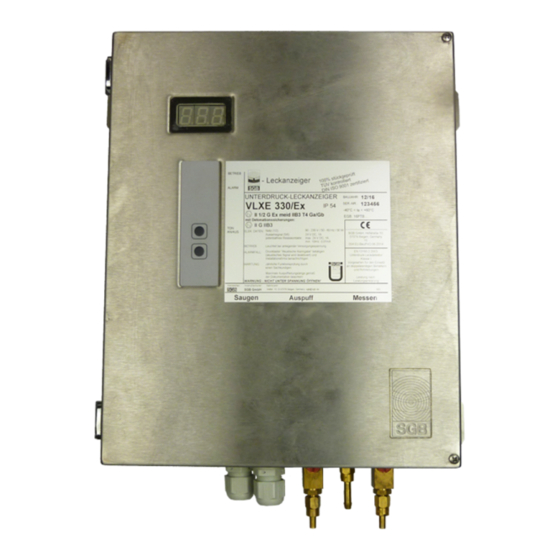
Design and Function Design and Function Design Interior view, with: Denotation flame arrester Three-way valve in suction line Three-way valve in the measuring line Vacuum pump Display board Keypad Pressure-resistant housing with control Separating barrier Data bus module (BM-i) Normal operating condition The vacuum leak detector is connected to the interstitial space via suction, measuring and connection line(s). -
Page 14: Air Leaks
Design and Function Air Leaks If an air leak occurs (in the outer or inner wall, above the liquid level), the vacuum pump switches on to restore the operating vacuum. If the leak causes the incoming air to exceed the pump’s capacity limit, the pump remains on continuously. -
Page 15: Displays And Controls
Design and Function Displays and Controls 4.6.1 Display Indicator light OPERA- TION: green ALARM: (flash- (flash- (flashing) ing) ing) ALARM 2: yellow (flash- Flashing ing) 4.6.2 Function "Turn off audible alarm signal" Briefly press “Mute“ button once; audible signal turns off, and the red LED flashes. - Page 16 Design and Function 4.6.4 “Tightness inquiry” function Press and hold the „Mute“ button until the signal lamp is flashing rap- idly, then release it. The display (103) will show a tightness value and (103) the same value will be indicated by the number of “Alarm” signal lamp flashes.
-
Page 17: Mounting The System
Mounting Mounting the System Basic Instructions - Prior to commencing work, the documentation must be read and understood. In case of ambiguities, please ask the manufacturer. - Observe the approvals of the manufacturer for the tank/pipeline and the interstitial space. - The safety instructions in this documentation must be adhered to. -
Page 18: Pneumatic Connection Lines
Mounting - Do not mount in access or inspection chambers. - The housing of the leak detector is integrated into the potential compensation. Pneumatic Connection Lines 5.3.1 Requirements - At least 6 mm inside clearance - Resistant to the stored or conveyed product - At least PN 10 over the total temperature range - The full cross section must be maintained (not bent) - Color coding: Measuring line: RED;... - Page 19 Mounting a liquid stop valve is not required if the end of the exhaust is in an area which is made liquid-tight (e.g. with collecting area). - Caution: An exhaust line which ends outdoors must not in any cir- cumstances be used to detect leaks (e.g., by “sniffing”).
-
Page 20: Completing Pneumatic Connections
5.4.1 Assembling the connection to the tank’s interstitial space. (1) Generally according to the tank manufacturer’s specifications. (2) SGB offers assembly kits with the various connection possibilities. 5.4.2 Assembling the connection to the pipelines interstitial space or test valves (1) Generally according to the pipelines/interstitial space manufac- turer's specifications. -
Page 21: Electrical Cables
Mounting (4) Hand-tighten union nut (5) Wrench-tighten union nut until need for increased force is notice- able (approx. 1 to 2 turns) Electrical Cables The electrical connection lines should be resistant to the existing or expected vapors and liquids. Cross section of 1.0 mm to 2.5 mm Outer cable diameter of 5.5 to 13 mm. - Page 22 Mounting 5.6.1 Connecting the wires (1) Insert a screwdriver into the opening above the point where the cable should be inserted. This opens the tension spring of the terminal. (2) Insert the cable into the open terminal. (3) Hold the cable and remove the screwdriver. (4) Check the cable for a tight fit and connect more cables to the terminals using the same process.
- Page 23 Mounting 5.6.4 Block diagram (SL 854 310) 24.1 "Power supply" fuse, 2 A Display 24.2 "Solenoid valve" fuse, 4 A Control unit 24.3 "External signal" fuse, 1 A Power supply unit 24 V DC Solenoid valve Keypad 59.2 Relay "External signal" Contacts for serial data transfer 59.3 Relay "Alarm"...
-
Page 24: Installation Examples
Mounting Installation Examples 5.7.1 Horizontal cylindrical tank with leak protection lining and suction line to low point Shut-off cock Exhaust Denotation flame arrester Three-way valve, suction line Three-way valve, measuring line Liquid stop valve Measuring line Suction line Interstitial space Nozzle for assembly pump Suction line to low point - 24 -... - Page 25 Mounting 5.7.2 Horizontal cylindrical tank, double-walled steel, without suction line to low point Shut-off cock Exhaust Denotation flame arrester Three-way valve, suction line Three-way valve, measuring line Liquid stop valve Measuring line Suction line Interstitial space Nozzle for assembly pump VACUUM LEAK DETECTOR VLXE ..
- Page 26 Mounting 5.7.3 Vertical cylindrical tank in accordance with DIN 6618-2 (downwards outside suction line) Shut-off cock Exhaust Denotation flame arrester Three-way valve, suction line Three-way valve, measuring line Liquid stop valve Condensate trap Measuring line Suction line Interstitial space Nozzle for assembly pump - 26 - VACUUM LEAK DETECTOR VLXE ..
- Page 27 Mounting 5.7.4 Double-walled pipe, connected in parallel, with solenoid valve in the suction line. To be used for conveyance pressures 5 bar > p < 25 bar in the inner pipe. Version VLXE .. Ex Shut-off cock Test valve Exhaust Suction line Denotation flame arrester Connection line...
- Page 28 Mounting 5.7.5 Double-walled pipe with solenoid valve in the connection line and additional pressure switch. To be used for conveyance pressures 25 bar > p < 90 bar in the inner pipe. Shut-off cock Suction line Exhaust Connection line Denotation flame arrester Nozzle for assembly pump Three-way valve, suction line Double-walled pipe...
- Page 29 Mounting 5.7.6 Double-walled pipe, connected in parallel (node point in the manifold) Shut-off cock Exhaust Denotation flame arrester Three-way valve, suction line Three-way valve, measuring line Liquid stop valve Liquid stop valve, connected against the flow direction Measuring line Solenoid valve Test valve Suction line Connection line...
- Page 30 Mounting 5.7.7 Double-walled pipe, connected in series ÜR 1 ÜR 2 Shut-off cock Exhaust Denotation flame arrester Three-way valve, suction line Three-way valve, measuring line Liquid stop valve Liquid stop valve, connected against the flow direction Measuring line Solenoid valve Test valve Suction line Connection line...
- Page 31 Mounting 5.7.8 Double-walled pipe, individual pipe with low vacuum VLXE 34 Ex Denotation flame arrester Three-way valve, suction line Three-way valve, measuring line Liquid stop valve Measuring line Test valve Suction line Connection line Double-walled pipe Pressure compensation vessel Node point Here: must (geodetically) be under 157 Lowest point of the interstitial space VACUUM-LEAK DETECTOR VLXE ..
-
Page 32: Commissioning
Commissioning Commissioning (1) Only perform commissioning once the steps in Section 5 “As- sembly” have been completed. (2) If a leak detector is operated on a interstitial space that is already in operation, special protective measures must be taken (for ex- ample, testing for gas freedom in the leak detector and/or the in- terstitial space). - Page 33 Commissioning (6) If the vacuum build-up is too slow, an assembly pump can be at- tached to the connection on three-way valve 20. Turn valve 180° and switch on the assembly pump. (7) After the operating vacuum of the leak detector has been reached (pump in leak detector shuts off), turn three-way valve 20 180°, switch off the assembly pump, and remove it.
-
Page 34: Functional Check And Maintenance
Functional Check and Maintenance Functional Check and Maintenance General (1) If the leak detection system has been properly installed and is free of leaks, trouble-free operation can be assumed. (2) Frequent switching on or continuous running of the pump indi- cates leaks, which should be corrected within a reasonable time. -
Page 35: Functional Check
- Testing of the probe (only VLXE .. Ex MMV LS) (7.3.9) - Creating the operating condition (7.3.10) - A test report must be completed, confirming functional and opera- tional safety. (Test reports are available for download for the SGB website) 7.3.1... - Page 36 Functional Check and Maintenance (1) Attach the measuring gauge to the connection on three-way valve 21 and turn valve 180°. (2) For pipelines: Open the test valve at the end opposite the leak detector; in case of multiple pipe interstitial spaces, the test valves must be opened sequentially at the end opposite the leak detector.
- Page 37 Determine the test period for each interstitial space connected (and/or the entire monitored system) (calculate or use test re- ports prepared by SGB GmbH). (2) Attach the measuring gauge to the connection on three-way valve 21 and turn valve 180°.
- Page 38 Functional Check and Maintenance (4) The test is considered passed if the vacuum does not drop by more than 1 mbar during the test period. Of course, a multiple of the test period can also be measured; in this case, the permissible vacuum drop is also a multiple. (5) Once the test is complete, return valves to their original positions and remove the measuring gauge.
- Page 39 Functional Check and Maintenance 7.3.9 Testing of the probe (only VLXE .. Ex MMV LS) (1) Bring the probe into the alarm state. Depending on the probe ver- sion, either by pressing a test button (“WHG probes”), by turning the housing (float), or by removing it and dipping it in test liquid. ...
-
Page 40: Malfunction (Alarm)
Malfunction (Alarm) Malfunction (Alarm) Alarm Description If an alarm goes off, one must assume that there is an explosive va- por-air mixture in the interstitial space. Take appropriate protective measures. (1) An alarm (vacuum loss) is indicated by the red “Alarm” signal lamp lighting up and the sounding of the audible signal, if availa- ble. -
Page 41: Spare Parts
Spare parts/Accessories/Disassembly and disposal Spare parts shop.sgb.de 10. Accessories For accessories, please refer to our website shop.sgb.de e.g. - Assembly kits - Electrical isolators - Manifolds - Testing device - Pressure booster 11. Disassembly and Disposal 11.1 Disassembly Prior to and during works, make sure the unit is free of gas and the... -
Page 42: Appendix
Appendix 12. Appendix 12.1 Use of Interstitial Spaces That Are Filled with Leak Detector Fluid 12.1.1 Requirements (1) Only leak detectors with suitable alarm pressures which depend on the tank diameter and the density of the stored material may be used. (2) The procedure described below is intended for the horizontal cy- lindrical tanks (e.g. -
Page 43: Appendix W, Warmed Tanks (Heated Tanks)
12.2.2 Tanks that need to be filled hot (T > 25°C) Calculation of the (possibly) required special switching valuesin coor- dination with SGB GmbH. Special switching values are intended to ensure that the alarm is triggered and that false alarms cannot occur. - Page 44 Appendix 12.2.3 Installation example of heated flat-bottomed tank (> 50°C ≤ 200°C) 01.2 50°< < 200°C "Alarm" indicator light, red Suction line 01.2 Signal lamp “Probe alarm”, yellow Buzzer (if installed) Shut-off cock „Mute“ button Exhaust line Interstitial space "Operation"...
- Page 45 Appendix 12.2.4 Installation example of heated horizontal cylindrical tank (> 50°C ≤ 200°C) 01.2 50°< < 200°C "Alarm" indicator light, red „Mute“ button 01.2 Signal lamp “Probe alarm”, yellow Interstitial space Shut-off cock Connection assembly pump Exhaust line Pressure compensation vessel (here: mounted inside the "Operation"...
-
Page 46: Dimensions And Drilling Pattern
Appendix 12.3 Dimensions and Drilling Pattern - 46 - VACUUM LEAK DETECTOR VLXE .. Ex M and VLXE .. Ex MMV 28/07/2020... -
Page 47: Declaration Of Conformity
Appendix 12.4 Declaration of Conformity SGB GmbH Hofstrasse 10 57076 Siegen, Germany, hereby declare in sole responsibility that the leak detectors VLXE .. A-Ex, VLXE .. Ex and VLXE .. Ex MMV is in conformity with the essential requirements of the EG directives listed below. -
Page 48: Declaration Of Performance
Use: Vacuum leak detector of class I for monitoring double-walled pipes and tanks Manufacturer: SGB GmbH, Hofstraße 10, 57076 Siegen, Germany Phone: +49 271 48964-0, e-mail: sgb@sgb.de Authorized representative: System for assessment and verification of constancy of performance: System 3... -
Page 49: Ex-Approval
Appendix 12.7 Ex-approval VACUUM LEAK DETECTOR VLXE .. Ex M and VLXE .. Ex MMV - 49 - 28/07/2020... - Page 50 Appendix - 50 - VACUUM LEAK DETECTOR VLXE .. Ex M and VLXE .. Ex MMV 28/07/2020...
- Page 51 Appendix VACUUM LEAK DETECTOR VLXE .. Ex M and VLXE .. Ex MMV - 51 - 28/07/2020...
- Page 52 Appendix - 52 - VACUUM LEAK DETECTOR VLXE .. Ex M and VLXE .. Ex MMV 28/07/2020...
-
Page 53: Certification Tüv-Nord
Appendix 12.8 Certification TÜV-Nord VACUUM LEAK DETECTOR VLXE .. Ex M and VLXE .. Ex MMV - 53 - 28/07/2020... - Page 54 Appendix - 54 - VACUUM LEAK DETECTOR VLXE .. Ex M and VLXE .. Ex MMV 28/07/2020...
- Page 55 Notes ______________________________________________________________________________________ ______________________________________________________________________________________ ______________________________________________________________________________________ ______________________________________________________________________________________ ______________________________________________________________________________________ ______________________________________________________________________________________ ______________________________________________________________________________________ ______________________________________________________________________________________ ______________________________________________________________________________________ ______________________________________________________________________________________ ______________________________________________________________________________________ ______________________________________________________________________________________ ______________________________________________________________________________________ ______________________________________________________________________________________ ______________________________________________________________________________________ ______________________________________________________________________________________ ______________________________________________________________________________________ ______________________________________________________________________________________ ______________________________________________________________________________________ ______________________________________________________________________________________ ______________________________________________________________________________________ ______________________________________________________________________________________ ______________________________________________________________________________________ ______________________________________________________________________________________ ______________________________________________________________________________________ ______________________________________________________________________________________ ______________________________________________________________________________________ ______________________________________________________________________________________ ______________________________________________________________________________________ VACUUM LEAK DETECTOR VLXE .. Ex M and VLXE .. Ex MMV - 55 - 28/07/2020...
- Page 56 Photos and sketches are not binding for +49 271 48964-0 the scope of delivery. Subject to change sgb@sgb.de - 56 - VACUUM LEAK DETECTOR VLXE .. Ex M and VLXE .. Ex MMV 28/07/2020 www.sgb.de without notice. © SGB GmbH, 07/2020...
Need help?
Do you have a question about the VLXE Ex M Series and is the answer not in the manual?
Questions and answers