
Subscribe to Our Youtube Channel
Related Manuals for SGB VL Series


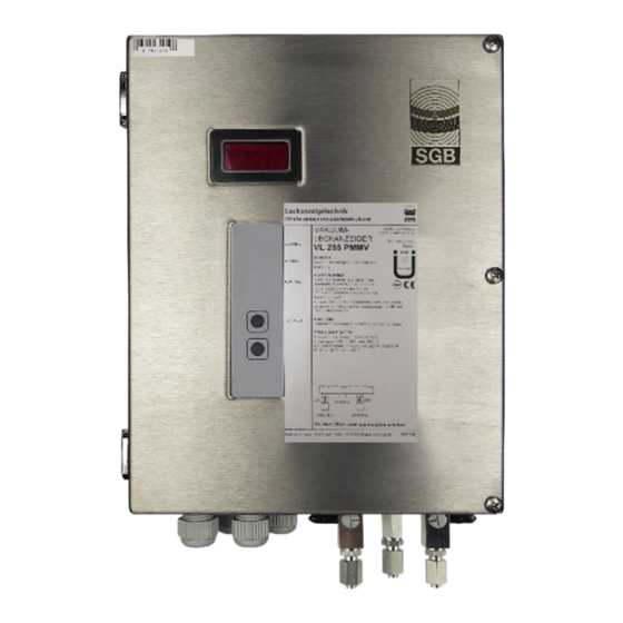
Summary of Contents for SGB VL Series
- Page 1 Documentation Vacuum leak detector VL .. in 100–240 VAC and 24 VDC Read instructions prior to commencing any work As of: 01/2020 Item no.: 605 322...
- Page 2 Variations/Options Overview of the Design Variations Vacuum leak detectors are available in different versions that are described more precisely by the letters attached to them. VL .. E FA P M MV LG LE S Si T “Tightness alarm” “Service Indication”: (LED) display with variably adjustable service periods “Service display”: integrated (LED) service display with fixed 12-month interval...
-
Page 3: Table Of Contents
Contents Table of Contents 1. General ..................5 1.1 Information ................ 5 1.2 Explanation of Symbols ............ 5 1.3 Limitation of Liability ............5 1.4 Copyright ................5 1.5 Warranty Conditions ............6 1.6 Customer Service ............. 6 2. Safety ..................7 2.1 ... - Page 4 Contents 10. Accessories ................40 11. Appendix .................. 41 11.1 Use of Interstitial Spaces That Are Filled with Leak Detector Fluid ............41 11.2 Appendix W, Warmed Tanks .......... 42 11.3 Dimensions and Drilling Pattern ........45 11.4 Declaration of Conformity ..........47 11.5 ...
-
Page 5: General
All information and instructions in this documentation have been compiled considering the applicable standards and regulations, the state of the art, and our longstanding experience. SGB does not assume any liability in the case of: Noncompliance with these instructions ... -
Page 6: Warranty Conditions
- modifications/repairs without consent of the manufacturer. 1.6 Customer Service Our customer service is available for any inquiries. For information on contacts, please refer to our website www.sgb.de or the label of the leak detector. - 6 - VACUUM LEAK DETECTOR VL .. -
Page 7: Safety
2.3 Qualification The personnel must be capable of independently recognizing and avoiding potential risks based on their qualifications. Companies commissioning leak detectors should have completed re- spective training with SGB, through SGB, or its authorized repre- sentative. WARNING! Danger to hu- National guidelines must be adhered to. -
Page 8: Personal Protective Equipment (Ppe)
Safety 2.4 Personal Protective Equipment (PPE) Personal protective equipment must be worn during work. o Wear necessary protective equipment for the relevant work o Note and comply with existing PPE signs Entry in the “Safety Book” Wear HV vest Wear safety footwear Wear hard hat Wear gloves –... - Page 9 Safety DANGER From working in chambers The leak detectors are mounted outside the access chambers. Pneumatic connection is usually performed inside the access cham- ber. Therefore, the chamber must be entered for mounting. Before entering, the corresponding protective measures must be tak- en and it must be ensured that no gas and sufficient oxygen are pre- sent.
-
Page 10: Technical Data Of The Leak Detector
- 570 mbar - 700 mbar - 900 mbar Special values can be agreed upon between the client and SGB. Excess pressure alarm (only VL .. MV ) at + 50 mbar * considered fulfilled for double-walled steel tanks; in principle, lower... -
Page 11: Field Of Application
Technical Data 3.4 Field of Application 3.4.1 Tank a) Single-walled horizontal (underground or aboveground) cylindrical tanks with leak protection lining (LAK) or jacket (LUM) and suction line leading to the low point Usage limits: None for density and diameter b) Double-walled horizontal cylindrical (underground or aboveground) tanks (e.g., DIN 6608-2, 6616, or DIN EN 12 285-1-2) - Same as a), but with no suction line to low point - Same as c), but with no suction line to low point... - Page 12 Technical Data Usage limits: Diameter Height Max. density of the stored material [mm] [mm] [kg/dm 330 to 570 2820 1.9 1.9 1.9 1.9 1600 3740 1.6 1.9 1.9 1.9 5350 ...
- Page 13 Technical Data e) Vertical cylindrical tanks with double-layered floor made of metal (e.g., according to DIN 4119 or EN 14015) - As above, but with leak protection lining (stiff or flexible) - Vertical cylindrical tanks made of plastic with double-layered floor Usage limits: None for density and diameter f) Tanks according to a) to d) that operate with an inner overlay...
-
Page 14: Design And Function
Design and Function 4. Design and Function 4.1 Design 4.1.1 Plastic housing interior view 01.2 Interior view with: Signal lamp “Alarm”, red 01.2 Signal lamp “Alarm 2” Signal lamp “Operation”, green Three-way valve, suction line Three-way valve, measuring line “Commissioning” key Vacuum pump Check valve with filter Buzzer... - Page 15 Design and Function 4.1.2 Stainless steel housing internal view Interior view with: Three-way valve, suction line Three-way valve, measuring line Vacuum pump Check valve with filter Buzzer “Mute” button Display board Main board 102 Pressure sensor 139 Keypad (on front) 144 Temperature switch, frost protection - 15 - VACUUM LEAK DETECTOR VL ..
-
Page 16: Normal Operating Condition
Design and Function 4.2 Normal Operating Condition The vacuum leak detector is connected to the interstitial space via suction, measuring, and connection lines. The vacuum generated by the pump is measured and controlled by a pressure sensor. When the operating vacuum is reached (Pump OFF), the pump shuts off. -
Page 17: Displays And Controls
Design and Function 4.6 Displays and Controls 4.6.1 Display Signal lamps OPERA- TION: green ALARM: (flash- (flash- (flashing) ing) ing) ALARM 2: yellow (flash- Flashing ing) 4.6.2 “Turn off audible alarm signal” function Briefly press “Mute” button once; audible signal turns off, and the red LED flashes. - Page 18 Design and Function 4.6.4 “Tightness inquiry” function Press and hold the “Mute” button until the signal lamp is flashing rap- idly, then release it. The display (103) will show a tightness value and (103) the same value will be indicated by the number of “Alarm” signal lamp flashes.
-
Page 19: Mounting The System
Mounting 5. Mounting the System 5.1 Basic Instructions o Prior to commencing work, the documentation must be read and understood. In case of ambiguities, please ask the manufacturer. o Observe the approvals of the manufacturer for the tank and the in- terstitial space. -
Page 20: Pneumatic Connection Lines
5.4 Completing Pneumatic Connections 5.4.1 Assembling the connection to the tank’s interstitial space (1) Generally according to the tank manufacturer’s specifications. (2) SGB offers assembly kits with the various connection possibili- ties. 5.4.2 Between leak detector and interstitial space (1) Select and install suitable pipe. -
Page 21: Electrical Cables
Mounting 5.4.2.1 Flanged screw connection (for flanged pipes) (1) Lubricate O-rings (2) Insert spacer ring loosely into the screw socket (3) Slide union nut and pressure ring over the pipe (4) Hand-tighten union nut (5) Tighten union nut until need for increased force is clearly notice- able (6) Final assembly: Tighten by another ¼... -
Page 22: Electrical Wiring Diagram
Mounting 5.6 Electrical Wiring Diagram (1) Fixed wiring, i.e., no plug or switch connections (2) Observe the requirements for electric installations, if necessary, also those of the electric companies. (3) Terminal layout: (see also SL854 851) PA PA PA Power connection (100–240 VAC) Occupied (vacuum pump) External signal, 24 VDC, can be disconnected Solenoid valve... - Page 23 Mounting 5.6.1 Connecting the Wires (1) Press down the orange point with a screwdriver. This opens the tension spring of the terminal (2) Insert the cable into the open terminal. (3) Hold the cable and remove the screwdriver. (4) Check the cable for a tight fit and install more cables to the ter- minals using the same process.
- Page 24 Mounting 5.6.3 Block diagram (SL 854 851) 100 - 240 V AC 50 Hz L 24 V DC 24 VDC Solenoid valve Vacuum pump (24 VDC) Main board Thermostat Heating Leak detection probe Pressure sensor Display Switching power supply Keypad Solenoid valve monitoring board (MVÜ...
-
Page 25: Installation Examples
Mounting 5.7 Installation Examples 5.7.1 Horizontal cylindrical tank with leak protection lining and suction line to low point Shut-off cock Exhaust line Three-way valve, suction line Three-way valve, measuring line Liquid stop valve Measuring line Suction line Interstitial space Connection assembly pump Suction line to low point VACUUM LEAK DETECTOR VL .. - Page 26 Mounting 5.7.2 Horizontal cylindrical tank, double-walled steel, without suction line to low point Shut-off cock Exhaust line Three-way valve, suction line Three-way valve, measuring line Liquid stop valve Measuring line Suction line Interstitial space Connection assembly pump - 26 - VACUUM LEAK DETECTOR VL ..
- Page 27 Mounting 5.7.3 Vertical cylindrical tank in accordance with DIN 6618-2 (downwards outside suction line) Shut-off cock Exhaust line Three-way valve, suction line Three-way valve, measuring line Liquid stop valve Condensate trap Measuring line Suction line Interstitial space Connection assembly pump Suction line to low point VACUUM LEAK DETECTOR VL ..
- Page 28 Mounting 5.7.4 Flat-bottomed tank structure Shut-off cock Exhaust line Three-way valve, suction line Three-way valve, measuring line Liquid stop valve Condensate trap Measuring line Suction line Interstitial space Connection assembly pump Suction line to low point - 28 - VACUUM LEAK DETECTOR VL .. 03/02/2020...
- Page 29 Mounting 5.7.5 Flat-bottomed tank structure, monitored using probe and solenoid valves 01.2 Signal lamp “Alarm”, red 01.2 Signal lamp “Alarm 2” Shut-off cock Signal lamp “Operation”, green (white) Three-way valve, suction line Three-way valve, measuring line Liquid stop valve Condensate trap “Commissioning”...
- Page 30 Mounting 5.7.6 Pressure Vessel 01.2 p < 25 bar - 30 - VACUUM LEAK DETECTOR VL .. 03/02/2020...
-
Page 31: Commissioning
Commissioning 6. Commissioning (1) Only perform commissioning once the steps in Section 5 “As- sembly” have been completed. (2) If a leak detector is operated on an interstitial space that is al- ready in operation, special protective measures must be taken (for example, testing for liquid freedom in the interstitial space). - Page 32 Commissioning (6) If the vacuum build-up is too slow, an assembly pump can be at- tached to the connection on three-way valve 20. Turn valve 180° and switch on the assembly pump. (7) After the operating vacuum of the leak detector has been reached (pump in leak detector shuts off), turn three-way valve 20 180°, switch off the assembly pump, and remove it.
-
Page 33: Functional Check And Maintenance
Functional Check and Maintenance 7. Functional Check and Maintenance 7.1 General (1) If the leak detection system has been properly installed and is free of leaks, trouble-free operation can be assumed. (2) Frequent switching on or continuous running of the pump indi- cates leaks, which should be corrected within a reasonable time. -
Page 34: Functional Check
Checking the probe (if used) (7.3.9) o Creating the operating condition (7.3.10) o A test report must be completed, confirming functional and opera- tional safety. Test reports are available for download from the SGB website. 7.3.1 Checking and emptying the condensate traps, if required CAUTION: The condensate traps may contain the stored/conveyed product. -
Page 35: Testing The Switching Values With The Interstitial Space (7.3.3)
Functional Check and Maintenance 7.3.2 Checking free passage in the interstitial space Checking the free passage of air ensures that an interstitial space is connected to the leak detector and that it has sufficient passage to cause an air leak to trigger an alarm. (1) Attach measuring gauge to connection on three-way valve 21 and turn valve 180°. -
Page 36: Testing The Switching Values With The Testing Device (7.3.4)
Functional Check and Maintenance 7.3.4 Testing the switching values with the testing device (see Section “Accessories”) (1) Connect the testing device to the two hose ends on each of the free connections of three-way valves 20 and 21. (2) Connect the measuring gauge to the T-piece of the testing de- vice. -
Page 37: System Tightness Test (7.3.6)
(1) The system tightness requirement is defined in Section 6.1. Determine the test period for each interstitial space connected (and/or the entire monitored system) (calculate or use test re- ports prepared by SGB GmbH). (2) Attach measuring gauge to connection on three-way valve 21 and turn valve 180°. -
Page 38: Checking The Probe (If Used) (7.3.9)
Functional Check and Maintenance (4) Pressure build-up until activation of the pressure switch (probe alarm is triggered and the solenoid valve switches). (5) Check the corresponding alarm(s). (6) Relieve pressure; probe alarm goes out and the solenoid valve switches. (7) Close the shut-off cock at 82 and remove the pressure booster. (8) Open the shut-off cock on the interstitial space side, put three- way valves 20 and 21 into operating position, and remove testing device. -
Page 39: Malfunction (Alarm)
Malfunction (Alarm) 8. Malfunction (Alarm) 8.1 Alarm Description If an alarm goes off, one must assume that there are vapors stored in the interstitial space. Take appropriate protective measures. (1) An alarm (vacuum loss) is indicated by the red “Alarm” signal lamp lighting up and the sounding of the audible signal, if availa- ble. -
Page 40: Spare Parts
Spare Parts/Accessories 9. Spare Parts See: sgb-shop.com 10. Accessories You can find accessories on our website sgb-shop.com, for example: - Installation kits - Electrical isolators - Manifolds - Testing devices - Pressure booster - 40 - VACUUM LEAK DETECTOR VL .. -
Page 41: Appendix
Appendix 11. Appendix 11.1 Use of Interstitial Spaces That Are Filled with Leak Detector Fluid 11.1.1 Requirements (1) Only leak detectors with suitable alarm pressures which depend on the tank diameter and the density of the stored material may be used. (2) The procedure described below is intended for horizontal cylin- drical tanks (e.g., DIN 6608, EN 12285-1, or comparable). -
Page 42: Appendix W, Warmed Tanks
11.2.2 Tanks that need to be filled hot (T > 25°C) Calculation of the (possibly) required special switching valuesin coor- dination with SGB GmbH. Special switching values are intended to ensure that the alarm is triggered and that false alarms cannot occur. - Page 43 Appendix 11.2.3 Installation example of heated flat-bottomed tank (> 50°C ≤ 200°C) 01.2 50°< < 200°C Signal lamp “Alarm”, red Suction line 01.2 Signal lamp “Probe alarm”, yellow Buzzer Shut-off cock “Sound off” key Exhaust line Interstitial space Signal lamp “Operation”, green Connection assembly pump Three-way valve, suction line...
- Page 44 Appendix 11.2.4 Installation example of heated horizontal cylindrical tank (> 50°C ≤ 200°C) 01.2 50°< < 200°C Signal lamp “Alarm”, red Buzzer 01.2 Signal lamp “Probe alarm”, yellow “Sound off” key Signal lamp “Operation”, green Interstitial space Detector pipe Pressure compensation vessel (here: mounted inside Three-way valve, suction line the isolation, i.e., needs to be warm due to fluidity)
-
Page 45: Dimensions And Drilling Pattern
Appendix 11.3 Dimensions and Drilling Pattern 11.3.1 Plastic housing VACUUM LEAK DETECTOR VL .. PMMV - 45 - 03/02/2020... - Page 46 Appendix 11.3.2 Stainless steel housing Ø8,5 - 46 - VACUUM LEAK DETECTOR VL .. 03/02/2020...
-
Page 47: Declaration Of Conformity
Appendix 11.4 Declaration of Conformity SGB GmbH Hofstrasse 10 57076 Siegen, Germany, hereby declare in sole responsibility that the leak detectors VL .. and VL .. MV are in conformity with the essential requirements of the EU directives listed below. -
Page 48: Declaration Of Performance
Vacuum leak detector type VL .. Use: Vacuum leak detector of class I for monitoring double-walled tanks Manufacturer: SGB GmbH, Hofstraße 10, 57076 Siegen, Germany Tel.: +49 271 48964-0, e-mail: sgb@sgb.de Authorized representative: System for assessment and verification of constancy of performance: System 3... -
Page 49: Tüv Nord Certification
Appendix 11.7 TÜV Nord Certification VACUUM LEAK DETECTOR VL .. PMMV - 49 - 03/02/2020... - Page 50 Notes ______________________________________________________________________________ ______________________________________________________________________________ ______________________________________________________________________________ ______________________________________________________________________________ ______________________________________________________________________________ ______________________________________________________________________________ ______________________________________________________________________________ ______________________________________________________________________________ ______________________________________________________________________________ ______________________________________________________________________________ ______________________________________________________________________________ ______________________________________________________________________________ ______________________________________________________________________________ ______________________________________________________________________________ ______________________________________________________________________________ ______________________________________________________________________________ ______________________________________________________________________________ ______________________________________________________________________________ ______________________________________________________________________________ ______________________________________________________________________________ ______________________________________________________________________________ ______________________________________________________________________________ ______________________________________________________________________________ ______________________________________________________________________________ ______________________________________________________________________________ ______________________________________________________________________________ - 50 - VACUUM LEAK DETECTOR VL .. 03/02/2020...
- Page 51 Notes ______________________________________________________________________________ ______________________________________________________________________________ ______________________________________________________________________________ ______________________________________________________________________________ ______________________________________________________________________________ ______________________________________________________________________________ ______________________________________________________________________________ ______________________________________________________________________________ ______________________________________________________________________________ ______________________________________________________________________________ ______________________________________________________________________________ ______________________________________________________________________________ ______________________________________________________________________________ ______________________________________________________________________________ ______________________________________________________________________________ ______________________________________________________________________________ ______________________________________________________________________________ ______________________________________________________________________________ ______________________________________________________________________________ ______________________________________________________________________________ ______________________________________________________________________________ ______________________________________________________________________________ ______________________________________________________________________________ ______________________________________________________________________________ ______________________________________________________________________________ _____________________________________________________________________________ VACUUM LEAK DETECTOR VL .. PMMV - 51 - 03/02/2020...
- Page 52 SGB GmbH Hofstrasse 10 57076 Siegen Germany Photos and sketches are not binding +49 271 48964-0 for the scope of delivery. Subject to sgb@sgb.de change without notice. © SGB GmbH, - 52 - VACUUM LEAK DETECTOR VL .. 03/02/2020 www.sgb.de 01/2020...
Need help?
Do you have a question about the VL Series and is the answer not in the manual?
Questions and answers