Advertisement
Quick Links
Advertisement

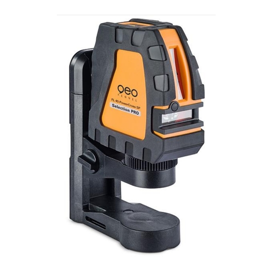
Summary of Contents for geo-FENNEL FL 40-PowerCross SP
- Page 1 FL 40-PowerCross SP Service Manual...
- Page 2 Service Manual FL 40-CrossPointer SP Contents 1. Service flow of the instrument 2.Accuracy calibration 2.1 Setting the reference 2.2 Sort of the error and calibration methods 3.Adjustment for alarming range 4.Disassembly and assembly of the instrument 4.1 Disassembly of the instrument 4.2 Circuit diagram 4.3 Assembly of the instrument...
- Page 3 Service Manual FL 40-CrossPointer SP 1、 Service flow of the instrument Service Contents Malfunction Cause Method step Appearance Step 1 Damage Change damaged parts the instrument 1.Mount the batteries 1. Change the polarity of Power on with wrongly(polarity) the battery Step 2 new battery, the Not lighted...
- Page 4 Service Manual FL 40-CrossPointer SP The reference should meet the requirements as follows: a) The debug platform should be in horizontal, the error is less than 5′ b) The centre of debug clamp is 5m from the wall, is 2.8m from plumb up dot and is 1m from plumb down dot.
- Page 5 Service Manual FL 40-CrossPointer SP and the horizontal reference line are parallel, i.e. parallel error, please calibrate as the follow methods: Note: observe whether there is error between the horizontal laser line and the adjacent light ruler reference. If there is error, please calculate the error into the reference on the wall. (if the adjacent light ruler laser line locates on +2, the laser line on wall reference locates on +2 too, it means the laser line is in horizontal in this direction, there is no need calibration.) 2.2.1.1.1 If the excursion is not more than 10mm, adjust the adjusting screw in two self check hole on point A...
- Page 6 Service Manual FL 40-CrossPointer SP Figure 4 2.2.2.1 The calibration of horizontal line gradient error 1)Put the instrument on the reference platform.Ppower on all laser indicators. 2)Rotate the unit, let the vertical laser line V approximately coincident with the reference line. 3)Observe the locations of the horizontal laser line and reference line on the wall.
- Page 7 Service Manual FL 40-CrossPointer SP 2.2.3 Curving error The laser line is curving to the reference line relatively, this error is curving error.(Figure 5) Figure 5 2.2.3.1 Calibration of curving error of horizontal laser line 1)Put the instrument on the reference platform. Power on all laser indicators. 2)Rotate the upper part of the unit, let the vertical laser line V is coincident with the reference line 3)Observe the locations of the laser line and reference line on the wall.
- Page 8 Service Manual FL 40-CrossPointer SP 3. Maintenance of alarming range Set up the instrument on adjustable inclined block, alarming range of all sides of the instrument are not coincident, and the relative differences between fore-and-aft and right-and-left is bigger, it will influence your usage, then it need to adjust again.
- Page 9 Service Manual FL 40-CrossPointer SP 1)Turn on the screw of the bracket part (6), take off the bracket part (6) from the main unit. 2)Use a cross screwdriver to turn off 4pcs cross-head plate tapping screw ST2.2x9.5(5), take off the housing module (1), unfix the connecting pin between the the 1# circuit board on the housing and the core part(3), disassemble the housing part(1) 3)Use a cross screwdriver to turn off 3 pcs cross-head plate tapping screw ST2.9x9.5(3), and take off the...
- Page 10 Service Manual FL 40-CrossPointer SP 4.1.3 Disassembly of the Core part(3) (Figure 9) Cross-head plate screws 3-1(2) 3-1(2) M2X5(6) 3# Connecting PC board 3-14(2) Gemel part/G609-gemel part 3-13 4#Alarming PC board/G609-4# Alarming PC board 3-12 Cross-head plate screws 3-1(2) 3-11(3) M2X8(2) 3-5(2) 3-10...
- Page 11 Service Manual FL 40-CrossPointer SP 8)Screw off 3pcs of fine adjusting screw M6X10(3-11)by a inner hexagon spanner, take off gemel part (G609-gemel part)(3-3) 4.1.4 The disassemble of the base part (4)(Figure 10) 4-1(2) 4-13 4-2(3) 4-12 4-3(6) 4-1(3) Cross-head plate tapping screws S2.2X5(5)...
- Page 12 Service Manual FL 40-CrossPointer SP 4.1.5 Disassembly of the bracket part(6) (Figure 11) 6-22 6-21 Lifting bracket 6-20 Locking sheet(2) Damping bracket 6-19(2) Cross head plate tapping screw 6-18(2) ST2.2X5(5) Locking ring 5 6-17 6-7(2) 6-16 Cross head plate tapping screw ST2.9X9.5(9)...
- Page 13 Service Manual FL 40-CrossPointer SP 4) Move off the Locking ring 5 (6-5) by a sharp-nose pliers, saperate the knob (6-20) 、 press cover ( 6-21) 、 cam(6-6) 5) Screw off 1 pc of cross-head plate tapping screw ST2.2X5 (6-4) by a cross srewdriver, move off damping bracket(6-3)...
- Page 14 Service Manual FL 40-CrossPointer SP 4.2 Circuit diagram Figure 11 As showed in figure 11,connect the corresponding connecting line to each PCBs accordingly.。 Solder 4 hairsprings to the corresponding place of4#Alarming PC board (or G609-4# Alarming PC board) (3-4)and 3# Connecting PC board.The hairspring is a 0.06mm(diameter)/80mm(length) brass wire.
- Page 15 Service Manual FL 40-CrossPointer SP 4.3. Assembly of the instrument The assembly of the instrument is the contrary process of its disassembly. Jointing of each screw need to rotate tightly, except for the situation that note especially. Requirement of assembly: a) Gelatinize 706 glue water on the jointing as follows: The interface between base(4-5)and inserting block(4-13)...


Need help?
Do you have a question about the FL 40-PowerCross SP and is the answer not in the manual?
Questions and answers