Advertisement
Available languages
Available languages
Table of Contents
- 1 Table of Contents
- 2 Assembly Tools Required
- 3 Part Identification
- 4 Hardware Identification
- 5 View the T-Lock Box Video
- 6 How to Use a Hidden Cam & Cam Dowel
- 7 Optional Hidden Wireless Qi Compatibile Charger by Eggtronic
- 8 Troubleshooting
- 9 Charger/Adapter/Outlet Defects
- 10 Installation Errors
- 11 Working Conditions - Phone/Case Issues
- Download this manual
CONTACT US FIRST
CONTACT US FIRST
sauder.com
sauder.com
sauder.com
BEFORE MAKING ANY RETURNS TO THE STORE.
BEFORE MAKING ANY RETURNS TO THE RETAILER.
sauder.com/service
Visit
Prefer the phone? Give us a ring at
Customer Service is available Monday-Friday - 9 a.m. to 5:30 p.m. EST (except holidays)
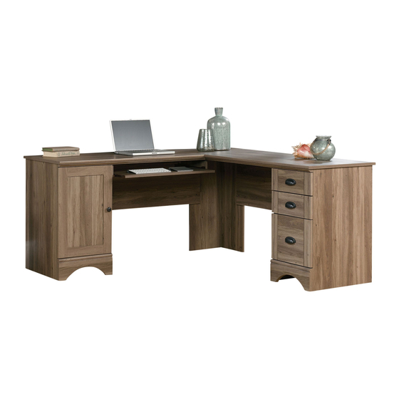
Corner Computer Desk
Harbor View Collection | Model 417586
Sauder.com
Share your journey!
to order replacement parts, view video assembly tips, or chat with a live rep.
1-800-523-3987
.
For all your
newfangled gadgetry.
NOTE: THIS INSTRUCTION
BOOKLET CONTAINS IMPORTANT
SAFETY INFORMATION.
PLEASE READ AND KEEP FOR
FUTURE REFERENCE.
English pg 1-56
Français pg 57-64
Español pg 65-72
Lot # 535570
Purchased: __________________
11/04/19
Advertisement
Table of Contents

Related Manuals for Sauder Harbor View 417586


Summary of Contents for Sauder Harbor View 417586
- Page 1 CONTACT US FIRST CONTACT US FIRST sauder.com sauder.com sauder.com BEFORE MAKING ANY RETURNS TO THE STORE. BEFORE MAKING ANY RETURNS TO THE RETAILER. sauder.com/service Visit to order replacement parts, view video assembly tips, or chat with a live rep. 1-800-523-3987 Prefer the phone? Give us a ring at Customer Service is available Monday-Friday - 9 a.m.
- Page 2 KEYBOARD SHELF (1) RIGHT DRAWER SIDE (1) MODESTY PANEL (2) BASE (2) LEFT DRAWER SIDE (1) BOTTOM (1) RIGHT MOLDING (1) DRAWER BACK (1) BACK (2) LEFT MOLDING (1) D109 SMALL DRAWER BACK (2) BRACE (2) Page 2 417586 www.sauder.com/service...
- Page 3 Part Identifi cation D109 D716 D109 D707 D716 www.sauder.com/service 417586 Page 3...
- Page 4 FILE GLIDE - 2 HIDDEN CAM - 18 METAL HIDDEN ANGLE CAM DOWEL - 18 CONNECTOR - 4 BRACKET - 4 BRACKET - 10 TIE PLATE - 2 13H HINGE - 2 KNOB - 1 PULL - 3 Page 4 417586 www.sauder.com/service...
- Page 5 BLACK 1-1/8" PAN HEAD SCREW - 10 15S SILVER 5/8" MACHINE SCREW - 6 18S BROWN 1" FLAT HEAD SCREW - 4 30S BLACK 1-9/16" FLAT HEAD SCREW - 12 GOLD 1" MACHINE SCREW - 1 www.sauder.com/service 417586 Page 5...
- Page 6 Look for this icon. It means a Step 1 video assembly tip is available at www.sauder.com/service/tips Assemble your unit on a carpeted fl oor or on the empty carton å to avoid scratching your unit or the fl oor. Fasten a DRAWER RIGHT (40AY) and a DRAWER LEFT (40AZ) å...
- Page 7 DRAWER SIDES (D24 and D25). Use four BLACK 1-9/16" FLAT HEAD SCREWS (30S). NOTE: Be sure the DRAWER BOTTOM (D716) inserts into å the groove of the DRAWER BACK (D109). Repeat this step for the other small drawer. å www.sauder.com/service 417586 Page 7...
- Page 8 Roller end (4 used for the PULLS) Screw head - turn CAM to line up holes in the SLIDES with holes in DRAWER SIDES Roller end GOLD 5/16" FLAT HEAD SCREW (8 used in this step) Page 8 417586 www.sauder.com/service...
- Page 9 Fasten the DRAWER BACK (D78) to the DRAWER SIDES (D28 and D29). Use four å BLACK 1-9/16" FLAT HEAD SCREWS (30S). NOTE: Be sure the DRAWER BOTTOM (D707) inserts into the groove of the å DRAWER BACK (D78). www.sauder.com/service 417586 Page 9...
- Page 10 SILVER 5/8" MACHINE SCREWS (15S). Roller end Screw head - turn CAM to line up holes in the SLIDES with holes in DRAWER SIDES Roller end (4 screws per drawer) GOLD 5/16" FLAT HEAD SCREW (4 used in this step) Page 10 417586 www.sauder.com/service...
- Page 11 Slide another FILE GLIDE (15B) onto the other end of the FILE å RODS (8B), then press this FILE GLIDE over the DRAWER LEFT SIDE (D29). Insert the FILE RODS into the holes of your choice in the FILE GLIDES, depending on your fi le sizes. www.sauder.com/service 417586 Page 11...
- Page 12 RIGHT" and "CABINET LEFT" for easy identifi cation. Insert four METAL PINS (1R) into the å DRAWER ENDS (C and D). GOLD 5/16" FLAT HEAD SCREW (12 used in this step) Roller end Small hole Roller end (4 used) Small hole Page 12 417586 www.sauder.com/service...
- Page 13 CAMS that are not CAMS that are not completely tightened completely tightened may loosen, and parts may loosen, and parts may separate. To may separate. To Minimum Minimum completely tighten: completely tighten: 190 degrees 190 degrees www.sauder.com/service 417586 Page 13...
- Page 14 Do not tighten the HIDDEN CAMS in this step. (12 used) BLACK 9/16" LARGE HEAD SCREW (4 used in this step) Arrow (4 used) Arrow Insert the metal end of the CAM DOWEL into the HIDDEN CAM. Page 14 417586 www.sauder.com/service...
- Page 15 B R A G L E i t h o E T S f a c S u r D E N H I D The ANGLE BRACKETS must be here. These holes must be here. www.sauder.com/service 417586 Page 15...
- Page 16 Fasten the BACK (K) to your unit using the NAILS (1N). å Edge without holes NOTE: Perforations have been provided for access å through the BACK. Carefully cut out the rectangle in the BACK for proper ventilation of your CPU. NAIL (15 used in this step) Page 16 417586 www.sauder.com/service...
- Page 17 Step 11 Fasten the BASE (X) to the DRAWER ENDS (C and D) å and BRACE (L). Use four BLACK 9/16" LARGE HEAD SCREWS (1S). BLACK 9/16" LARGE HEAD SCREW (4 used in this step) www.sauder.com/service 417586 Page 17...
- Page 18 Do not tighten the HIDDEN CAMS in this step. (8 used) BLACK 9/16" LARGE HEAD SCREW (4 used in this step) Arrow (4 used) Arrow Insert the metal end of the CAM DOWEL into the HIDDEN CAM. Page 18 417586 www.sauder.com/service...
- Page 19 S u r f a c H I D D E N i t h i t h o f a c S u r D E N H I D These holes must be here. www.sauder.com/service 417586 Page 19...
- Page 20 Fasten the BACK (K) to your unit using the NAILS (1N). å Edge without holes NOTE: Perforations have been provided for access å through the BACK. Carefully cut out the rectangle in the BACK for proper ventilation of your CPU. NAIL (15 used in this step) Page 20 417586 www.sauder.com/service...
- Page 21 Step 15 Fasten the BASE (X) to the DOOR ENDS (A and B) å and BOTTOM (J). Use four BLACK 9/16" LARGE HEAD SCREWS (1S). BLACK 9/16" LARGE HEAD SCREW (4 used in this step) www.sauder.com/service 417586 Page 21...
- Page 22 Push two HIDDEN CAMS (1F) into the UPRIGHTS (E and F), å and BOTTOM (J). Then, insert the metal end of a CAM DOWEL (2F) into each HIDDEN CAM. Arrow Do not tighten the HIDDEN CAMS in this step. (2 used) Page 22 417586 www.sauder.com/service...
- Page 23 Do not stand the unit upright without the BACK fastened. The unit may collapse. BLACK 1-7/8" FLAT HEAD SCREW (2 used in this step) Edge with CAM DOWEL S u r f a c H I D D E N i t h www.sauder.com/service 417586 Page 23...
- Page 24 SMALL TOP (H3) and the ENDS (C and D) to the TOP (G3) as shown in the lower diagram. DOOR ON LEFT AND DRAWERS ON RIGHT Follow STEPS 19-25 DOOR ON RIGHT AND DRAWERS ON LEFT Follow STEPS 26-32 Page 24 417586 www.sauder.com/service...
- Page 25 Fasten the DOOR ENDS (A and B) to the TOP (G3). DOOR ON LEFT AND å Tighten four HIDDEN CAMS. DRAWERS ON RIGHT Maximum Arrow 210 degrees Minimum 190 degrees The through hole must be here. www.sauder.com/service 417586 Page 25...
- Page 26 H I D f a c D E N i t h S u r D E N BLACK 1-1/8" PAN HEAD SCREW H I D (3 used in this step) Flat end Page 26 417586 www.sauder.com/service...
- Page 27 Use two BLACK 1-7/8" FLAT HEAD SCREWS (2S). Cut-out BLACK 1-1/8" PAN HEAD SCREW (2 used in this step) BLACK 1-7/8" FLAT HEAD SCREW (2 used in this step) Use a 1/8" drill bit to fi nish drilling these holes completely through. www.sauder.com/service 417586 Page 27...
- Page 28 å cord against the TOP. The CORD CLIP for this hole will be inserted in Step 36 after the two TOPS are attached. Use these holes. BLACK 9/16" LARGE HEAD SCREW (6 used in this step) Page 28 417586 www.sauder.com/service...
- Page 29 Step Step 23 Fasten the DRAWER ENDS (C and D) to the SMALL å DOOR ON LEFT AND TOP (H3). Tighten four HIDDEN CAMS. DRAWERS ON RIGHT Maximum Arrow 210 degrees Minimum 190 degrees Large hole www.sauder.com/service 417586 Page 29...
- Page 30 HEAD SCREWS (1S). Use a 1/8" drill bit to fi nish drilling these holes completely through. BLACK 1-7/8" FLAT HEAD SCREW (2 used for the MODESTY PANEL) BLACK 9/16" LARGE HEAD SCREW (2 used for the ANGLE BRACKET) Page 30 417586 www.sauder.com/service...
- Page 31 Turn a CORD CLIP (4P) into the TOP (H3). å NOTE: The CORD CLIP is used to hold your keyboard cord å against the TOP. BLACK 1-1/8" PAN HEAD SCREW (3 used in this step) Angled end www.sauder.com/service 417586 Page 31...
- Page 32 Fasten the DRAWER ENDS (C and D) to the TOP (G3). DOOR ON RIGHT AND å Tighten four HIDDEN CAMS. DRAWERS ON LEFT Maximum Arrow 210 degrees Minimum 190 degrees The through hole must be here. Page 32 417586 www.sauder.com/service...
- Page 33 H I D i t h D E N i t h BLACK 1-1/8" PAN HEAD SCREW f a c S u r D E N (3 used in this step) H I D Flat end www.sauder.com/service 417586 Page 33...
- Page 34 Use two BLACK 1-7/8" FLAT HEAD SCREWS (2S). BLACK 1-1/8" PAN HEAD SCREW (2 used in this step) BLACK 1-7/8" FLAT HEAD SCREW (2 used in this step) Use a 1/8" drill bit to fi nish drilling these holes completely through. Page 34 417586 www.sauder.com/service...
- Page 35 å cord against the TOP. The CORD CLIP for this hole will be inserted in Step 36 after the two TOPS are attached. Use these holes. BLACK 9/16" LARGE HEAD SCREW (6 used in this step) www.sauder.com/service 417586 Page 35...
- Page 36 Step 30 Fasten the DOOR ENDS (A and B) to the SMALL DOOR ON RIGHT AND å TOP (H3). Tighten four HIDDEN CAMS. DRAWERS ON LEFT Maximum Arrow 210 degrees Minimum 190 degrees Large hole Page 36 417586 www.sauder.com/service...
- Page 37 HEAD SCREWS (1S). Use a 1/8" drill bit to fi nish drilling these holes completely through. BLACK 1-7/8" FLAT HEAD SCREW (2 used for the MODESTY PANEL) BLACK 9/16" LARGE HEAD SCREW (2 used for the ANGLE BRACKET) www.sauder.com/service 417586 Page 37...
- Page 38 DRAWERS ON LEFT Turn a CORD CLIP (4P) into the TOP (H3). å NOTE: The CORD CLIP is used to hold your keyboard cord å against the TOP. BLACK 1-1/8" PAN HEAD SCREW (3 used in this step) Page 38 417586 www.sauder.com/service...
- Page 39 The embedded wireless charging system is designed for the following smartphones: • Apple (iPhone 8 or newer) • Samsung (Galaxy 6 or newer) • For a complete compatibility list, go to sauder.com. If you did not purchase the optional Hidden Wireless Qi Compatible Charger by Eggtronic, go to å...
- Page 40 The STICKER will be centered in this cut-out circle. L'AUTOCOLLANT sera centré dans ce cercle découpé. La ETIQUETA se centrará en este círculo recortado. FRONT EDGE OF TOP (G3) CHANT AVANT DU DESSUS (G3) BORDE DELANTERO DEL PANEL SUPERIOR (G3) Page 40 417586 www.sauder.com/service...
- Page 41 This page was intentionally left blank. Cette page a été intentionnellement laissée vierge. Esta página fue dejada en blanco intencionalmente. www.sauder.com/service 417586 Page 41...
- Page 42 The STICKER will be centered in this cut-out circle. L'AUTOCOLLANT sera centré dans ce cercle découpé. La ETIQUETA se centrará en este círculo recortado. FRONT EDGE OF TOP (H3) CHANT AVANT DU DESSUS (H3) BORDE DELANTERO DEL PANEL SUPERIOR (H3) Page 42 417586 www.sauder.com/service...
- Page 43 This page was intentionally left blank. Cette page a été intentionnellement laissée vierge. Esta página fue dejada en blanco intencionalmente. www.sauder.com/service 417586 Page 43...
- Page 44 "Changes or modifi cations not expressly approved by the party responsible for compliance could void the user's authority to operate this device". "Changes or modifi cations not expressly approved by Sauder Woodworking Co. could void the user's authority to operate this device".
- Page 45 The sides of the CHARGER will expand into the sides of the large hole as you tighten the SCREWS. The sides of the CHARGER will expand into the sides of the large hole as you tighten the SCREWS. www.sauder.com/service 417586 Page 45...
- Page 46 Turn a CORD CLIP (4P) into the TOP (G3). å BLACK 9/16" LARGE HEAD SCREW (4 used for the SMALL TOP) Insert the CORD CLIP after the two TOPS are attached. BLACK 1-1/8" PAN HEAD SCREW (2 used for the RIGHT UPRIGHT) Page 46 417586 www.sauder.com/service...
- Page 47 Step 37 Fasten two HINGES (13H) to the DOOR (M). Use four å BLACK 1/2" FLAT HEAD SCREWS (11S). BLACK 1/2" FLAT HEAD SCREW (4 used in this step) www.sauder.com/service 417586 Page 47...
- Page 48 Peel the FELT DISC from the FELT DISC CARD (1M). Stick å a FELT DISC on the DOOR where it comes in contact with the DOOR RIGHT END (A). See the next step for DOOR adjustments. å GOLD 1" MACHINE SCREW (1 used for the KNOB) Page 48 417586 www.sauder.com/service...
- Page 49 To adjust the DOORS in or out (depth), loosen the mounting screw å one turn and move the DOORS in or out, as needed. Tighten the mounting screw after making adjustments. Mounting screw (depth) Adjusting screw (horizontal) (vertical adjustment) www.sauder.com/service 417586 Page 49...
- Page 50 Insert a CONNECTOR SCREW (8S) into each å HIDDEN CONNECTOR (9F). Step 41 Use your hammer to tap four HIDDEN CONNECTORS (9F) å with SCREWS into the KEYBOARD UPRIGHTS (Q2). STOP If you purchased the 417587 Hutch, assemble that unit fi rst. Page 50 417586 www.sauder.com/service...
- Page 51 NOTE: Be sure the edges of the METAL BRACKETS are even å with the edges of the KEYBOARD UPRIGHTS. GOLD 5/16" FLAT HEAD SCREW (4 used for the CABINET RAILS) Roller end Roller end BLACK 9/16" LARGE HEAD SCREW (4 used for the METAL BRACKETS) www.sauder.com/service 417586 Page 51...
- Page 52 BLACK 9/16" LARGE HEAD SCREW (4 used for the METAL BRACKETS) Roller end The KEYBOARD SHELF can be fastened to the left side, center, or right side. Page 52 417586 www.sauder.com/service...
- Page 53 Lift the front of the drawer up and slide it into the unit. Repeat this step to insert the KEYBOARD SHELF. 10 lbs. each (4 used) 50 lbs. 30 lbs. www.sauder.com/service 417586 Page 53...
- Page 54 TOP. STOP The STICKER Center the STICKER inside must be placed the cut-out hole in the directly above the LEFT STICKER TEMPLATE. CHARGER. Center the STICKER inside the cut-out hole in the RIGHT STICKER TEMPLATE. Page 54 417586 www.sauder.com/service...
- Page 55 å This completes assembly. Clean with a damp cloth. Wipe dry. å And to celebrate, why not share your success story at sauder.com or Scan this QR code or go to this address: http://qr.sauder.com/?ID=2631 Loosen screw #3 a 1/4 turn, turn the cam a 1/4 turn to leave feedback on assembly experience.
- Page 56 (IF ANY SOUND, THEN SECTION A IS NOT THE ISSUE) (IF NO SOUND, THEN ISSUE IS IN SECTIONS A OR B) (normal conditions: one single beep when charging starts) 17) Is the smartphone correctly aligned with the charging spot? (normal conditions: yes) Page 56 417586 www.sauder.com/service...
- Page 57 QUANTITÉ REFERENCE DESCRIPTION QUANTITÉ conserver le livret pour future référence. Pour contacter Sauder en EXTRÉMITÉ DROITE DE PORTE ......1 40AW ÉLÉMENT DROITE............1 EXTRÉMITÉ GAUCHE DE PORTE ....1 40AX ÉLÉMENT GAUCHE ...........1 ce qui concerne cet EXTRÉMITÉ DROITE DE TIROIR .......1 40AY TIROIR DROIT ..............1...
- Page 58 3. Attention: Risque des dégâts ou blessures. Les EXCENTRIQUES ESCAMOTABLES doivent être serrés à bloc. Les EXCENTRIQUES ESCAMOTABLES que ne sont pas serrées à bloc peuvent desserrer et les pièces peuvent séparer. Pour serrer à bloc : Page 58 417586 www.sauder.com/service...
- Page 59 CHEVILLE D'EXCENTRIQUE (2F) dans chaque EXCENTRIQUE ESCAMOTABLE. Fixer quatre CONSOLES À ÉQUERRE (5G) aux EXTRÉMITÉS (A et B) et au DESSOUS (J). Utiliser quatre VIS TÊTE LARGE 14 mm NOIRES (1S). www.sauder.com/service 417586 Page 59...
- Page 60 TIROIR (D). Utiliser deux VIS TÊTE PLATE 48 mm NOIRES (2S). Fixer une CONSOLE À ÉQUERRE (5G) sur le PETIT DESSUS (H3) et le VOILE DE FOND (I). Utiliser deux VIS TÊTE LARGE 14 mm NOIRES (1S). Page 60 417586 www.sauder.com/service...
- Page 61 VIS TÊTE GOUTTE DE SUIF 28 mm NOIRES (9S). Serrer un CLIP DE CORDONS (4P) dans le DESSUS (H3). REMARQUE : Le CLIP DE CORDON est utilisé pour maintenir le cordon de clavier contre le DESSUS. www.sauder.com/service 417586 Page 61...
- Page 62 Chargez votre téléphone en le posant simplement ménagers. Lire attentivement l'information suivante sur la sécurité. sur votre meuble. Pour l'acheter, allez sur le site Web sauder.com • ÉVITER de faire tomber Liste de smartphones approuvés compatibles Qi •...
- Page 63 Pour insérer les tiroirs dans l'élément, abaisser le devant du tiroir et faire passer les roulettes situées sur le tiroir derrière les roulettes situées sur l'élément. Relever le devant du tiroir et l'enfi ler dans l'élément. Répéter cette étape pour insérer la TABLETTE DE CLAVIER. www.sauder.com/service 417586 Page 63...
- Page 64 (SI ABSENCE DE SON. LE PROBLÈME SE TROUVE DANS LA SECTION A OU B) (conditions normales : un seul bip quand le chargeur démarre) 17) Le smartphone est-il correctement aligné sur le point de charge ? (conditions normales : oui) Page 64 417586 www.sauder.com/service...
- Page 65 EXTREMO IZQUIERDO DE PUERTA ......1 VARILLA DE ARCHIVERO ..........2 necesita ponerse en EXTREMO DERECHO DE CAJÓN ......1 CORRIMIENTO DE ARCHIVERO........ 2 contacto con Sauder en EXCÉNTRICO ESCONDIDO ........18 EXTREMO IZQUIERDO DE CAJÓN ......1 PASADOR DE EXCÉNTRICO ........18 cuanto a esta unidad, PARAL DERECHO ..............
- Page 66 ESCONDIDOS deben apretarse completamente. Los EXCÉNTRICOS NOTA: Asegúrese que el FONDO DE CAJÓN (D707) ajuste dentro ESCONDIDOS que no se aprieten completamente se afl ojarán y las de la ranura del DORSO DE CAJÓN (D78). partes pueden separarse. Para apretar completamente: Page 66 417586 www.sauder.com/service...
- Page 67 PASADOR DE EXCÉNTRICO (2F) dentro de cada EXCÉNTRICO ESCONDIDO. Fije cuatro SOPORTES ANGULARES (5G) a los EXTREMOS (A y B) y al FONDO (J). Utilice cuatro TORNILLOS NEGROS DE CABEZA GRANDE de 14 mm (1S). www.sauder.com/service 417586 Page 67...
- Page 68 CAJÓN (D). Utilice dos TORNILLOS NEGROS DE CABEZA PERDIDA de 48 mm (2S). Fije un SOPORTE ANGULAR (5G) al PANEL SUPERIOR PEQUEÑO (H3) y al VELO DE FONDO (I). Utilice dos TORNILLOS NEGROS DE CABEZA GRANDE de 14 mm (1S). Page 68 417586 www.sauder.com/service...
- Page 69 PEQUEÑO (H3). Utilice tres TORNILLOS NEGROS DE CABEZA REDONDA de 28 mm (9S). Atornille una GRAPA DE CABLE (4P) en el PANEL SUPERIOR (H3). NOTA: Se utiliza la GRAPA DE CABLE para mantener los cordones de teclado contra el PANEL SUPERIOR. www.sauder.com/service 417586 Page 69...
- Page 70 Lea Cargue su teléfono simplemente colocándolo en la parte superior cuidadosamente la siguiente información de seguridad. de sus muebles. Para comprar, vaya al sauder.com. • EVITAR dejar caer Lista de Teléfonos Inteligentes Aprobados Compatibles con Qi •...
- Page 71 Levante la parte delantera del cajón y deslícelo dentro de la unidad. Repita este paso para insertar el ESTANTE DE TECLADO. www.sauder.com/service 417586 Page 71...
- Page 72 (SI NO HAY SONIDO, ENTONCES EL PROBLEMA ESTÁ EN LAS SECCIONES A O B) (condiciones normales: un solo pitido cuando se inicia la carga) 17) ¿El teléfono inteligente está alineado correctamente con el punto de carga? (condiciones normales: sí) Page 72 417586 www.sauder.com/service...
- Page 73 à Les téléviseurs peuvent être particulièrement un téléviseur. cet eff et. lourds. De plus, le poids et l’emplacement du tube image ont tendance à rendre les téléviseurs instables et enclins à tomber vers l’ a vant. www.sauder.com/service 417586 Page 73...
- Page 74 Además, el peso y la ubicación del tubo de imagen tienden a causar la inestabilidad de televisores y propensa a volcarse hacia adelante. Page 74 417586 www.sauder.com/service...
- Page 75 à compter de la date d'achat la première fois et qui sont signalés à Sauder dans les limites de couverture de la contre tout défaut de matériaux ou de fabrication des composantes de mobilier Sauder.
- Page 76 BEFORE MAKING ANY RETURNS TO THE RETAILER. Dear Valued Customer: So, how did it go? Thanks so much for choosing Sauder® furniture. I hope the Set a world record for speed? purchase and assembly process was a positive experience Feeling good about yourself? and you feel good about the furniture you just built.
Need help?
Do you have a question about the Harbor View 417586 and is the answer not in the manual?
Questions and answers