Advertisement
Quick Links
CONTACT US FIRST
CONTACT US FIRST
sauder.com
sauder.com
sauder.com
BEFORE MAKING ANY RETURNS TO THE STORE.
BEFORE MAKING ANY RETURNS TO THE RETAILER.
sauder.com/service
Visit
Prefer the phone? Give us a ring at
Customer Service is available Monday-Friday - 9 a.m. to 5:30 p.m. EST (except holidays)
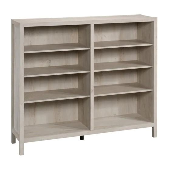
Bookcase
Pacific View Collection | Model 427044
Sauder.com
Share your journey!
to order replacement parts, view video assembly tips, or chat with a live rep.
1-800-523-3987
.
The stories of your life.
NOTE: THIS INSTRUCTION
BOOKLET CONTAINS IMPORTANT
SAFETY INFORMATION.
PLEASE READ AND KEEP FOR
FUTURE REFERENCE.
English pg 1-28
Français pg 29-32
Español pg 33-36
Lot # 542627
03/26/20
Purchased: __________________
Advertisement

Related Manuals for Sauder Pacific View 427044


Summary of Contents for Sauder Pacific View 427044
- Page 1 CONTACT US FIRST CONTACT US FIRST sauder.com sauder.com sauder.com BEFORE MAKING ANY RETURNS TO THE STORE. BEFORE MAKING ANY RETURNS TO THE RETAILER. sauder.com/service Visit to order replacement parts, view video assembly tips, or chat with a live rep. 1-800-523-3987 Prefer the phone? Give us a ring at Customer Service is available Monday-Friday - 9 a.m.
- Page 2 Table of Contents Assembly Tools Required Part Identification No. 2 Phillips Screwdriver Tip Shown Actual Size Hardware Identification Assembly Steps 5-28 Hammer Français 29-32 Not actual size Español 33-36 Safety 37-38 Warranty Page 2 427044 www.sauder.com/service...
- Page 3 SIDE MOLDING (4) RIGHT SHELF (1) BOTTOM (1) BOTTOM FRONT MOLDING (1) LEFT SHELF (1) LEFT FRONT/RIGHT REAR LEG (2) UPRIGHT MOLDING (1) ADJUSTABLE SHELF (4) RIGHT FRONT/LEFT REAR LEG (2) TOP REAR MOLDING (1) BACK (1) www.sauder.com/service 427044 Page 3...
-
Page 4: Table Of Contents
APPLIQUE CARD - 4 METAL PIN - 16 RUBBER SLEEVE - 16 RESTRAINT KIT - 1 BLACK 9/16" LARGE HEAD SCREW - 8 SILVER 1-1/8" FLAT HEAD SCREW - 8 113S BLACK 1-15/16" FLAT HEAD SCREW - 6 Page 4 427044 www.sauder.com/service... - Page 5 Push a HIDDEN CAM into Insert the CAM SCREW into the HIDDEN CAM. the part. The arrow in the Tighten the HIDDEN CAM. HIDDEN CAM must point toward the hole in the edge of the board. Hole www.sauder.com/service 427044 Page 5...
- Page 6 Step 1 Look for this icon. It means a video assembly tip is available at www.sauder.com/service/tips Find the numbered video or scan the QR code. å Assemble your unit on a carpeted floor or on the empty carton to avoid scratching your unit or the floor.
- Page 7 Step 2 å Turn three CAM SCREWS (8F) into the UPRIGHT MOLDING (J). å Fasten the UPRIGHT MOLDING (J) to the UPRIGHT (L). Tighten three HIDDEN CAMS. www.sauder.com/service 427044 Page 7...
- Page 8 Slide the BOTTOM FRONT MOLDING* (H) onto the notched edge of the BOTTOM (C). å *U.S. Patent No. 5,499,886 Notched edge Slide the MOLDING (H) onto the notched edge. The groove is closer to this edge. These surfaces should be even. Page 8 427044 www.sauder.com/service...
-
Page 9: 34E
S u r D E N H I D 113S BLACK 1-15/16" FLAT HEAD SCREW (2 used for the UPRIGHT) BLACK 9/16" LARGE HEAD SCREW (4 used for the ADJUSTABLE FOOT) www.sauder.com/service 427044 Page 9... -
Page 10: Hidden Cam
Push eight HIDDEN CAMS (1F) into the SHELVES (M and N). Then, insert the metal end of a CAM DOWEL (2F) into each HIDDEN CAM. Do not tighten the HIDDEN CAMS in this step. Arrow Metal end Arrow Metal end Page 10 427044 www.sauder.com/service... - Page 11 H I D D E N i t h Unfinished edge S u r f a c H I D D E N i t h For support, place packing foam and magazines here. www.sauder.com/service 427044 Page 11...
- Page 12 Step 7 å Push ten HIDDEN CAMS (1F) into one END (A). Arrow Arrow (20 used) Arrow Page 12 427044 www.sauder.com/service...
- Page 13 å NOTE: Do not overtighten the SCREWS into the MOLDING. SILVER 1-1/8" FLAT HEAD SCREW (4 used in this step) The MOLDING will overhang the edge of the END. The hole is closer to this edge. www.sauder.com/service 427044 Page 13...
- Page 14 Step 9 å Turn sixteen CAM SCREWS (8F) into the LEGS (D and E). å Insert eight WOOD DOWELS (15F) into the LEGS (D and E). (16 used) Page 14 427044 www.sauder.com/service...
-
Page 15: Connector
LEGS (D and E). Now might be a good time to refresh your drink. Use your hammer to gently tap the MOLDING CONNECTORS (16F) into the notches in the LEGS. Flat end Flat end www.sauder.com/service 427044 Page 15... - Page 16 NOTE: Be sure the WOOD DOWELS in the LEGS insert into the END. i t h f a c S u r D E N H I D These surfaces should be even. The LEGS will overhang this edge. Page 16 427044 www.sauder.com/service...
- Page 17 S u r D E N H I D i t h o f a c S u r D E N H I D 113S BLACK 1-15/16" FLAT HEAD SCREW (4 used for the BOTTOM) www.sauder.com/service 427044 Page 17...
- Page 18 Step 13 å Push eight HIDDEN CAMS (1F) into the TOP (B). Arrow Arrow Page 18 427044 www.sauder.com/service...
- Page 19 CAM in the edges of the ENDS (A) and UPRIGHT (L). å Fasten the TOP (B) to the ENDS (A) and UPRIGHT (L). Tighten six HIDDEN CAMS. Metal end S u r f a c w i t h H I D D E N www.sauder.com/service 427044 Page 19...
- Page 20 NOTE: You should start each SCREW a few turns before completely tightening any of them. The hole is closer to this edge. Safety strap SILVER 1-1/8" FLAT HEAD SCREW (4 used for the MOLDINGS) These surfaces should be even. Page 20 427044 www.sauder.com/service...
- Page 21 Step 16 å Turn four CAM SCREWS (8F) into the TOP REAR MOLDING (K). å Insert three WOOD DOWELS (15F) into the TOP REAR MOLDING (K). www.sauder.com/service 427044 Page 21...
- Page 22 Fasten the TOP REAR MOLDING (K) to the TOP (B). Tighten four HIDDEN CAMS. å NOTE: Be sure the WOOD DOWELS in the MOLDING insert into the TOP. NOTE: Be sure the MOLDING CONNECTORS in the LEGS insert into the MOLDING. Page 22 427044 www.sauder.com/service...
- Page 23 BLACK 9/16" LARGE HEAD SCREW (4 used for the BOTTOM and MOLDING) Safety strap Before fastening the BACK, punch out the perforation and push the SAFETY STRAP through the hole. These holes must line up over the UPRIGHT (L). www.sauder.com/service 427044 Page 23...
- Page 24 Step 19 å Turn four CAM SCREWS (8F) into the TOP FRONT MOLDING (F). Almost time to å Insert three WOOD DOWELS (15F) into the celebrate! With a nap. TOP FRONT MOLDING (F). Page 24 427044 www.sauder.com/service...
- Page 25 Fasten the TOP FRONT MOLDING (F) to the TOP (B). Tighten four HIDDEN CAMS. å NOTE: Be sure the WOOD DOWELS in the MOLDING insert into the TOP. NOTE: Be sure the MOLDING CONNECTORS in the LEGS insert into the MOLDING. www.sauder.com/service 427044 Page 25...
- Page 26 FOOT (34E) downward until it touches the floor. å IMPORTANT: The ADJUSTABLE FOOT should not extend beyond the bottom edges of the LEGS (D and E). With your No. 2 Phillips Screwdriver, turn the ADJUSTABLE FOOT downward until it touches the floor. Floor Page 26 427044 www.sauder.com/service...
- Page 27 5. Continue to turn until the screw starts spinning freely. å NOTE: Before moving your unit to a different location, unscrew the SAFETY DRYWALL ANCHOR from your wall. The nylon sheath will remain behind your wall. Safety drywall anchor Safety strap Washer www.sauder.com/service 427044 Page 27...
- Page 28 NOTE: Please read the back pages of the instruction booklet for important safety information. å This completes assembly. Clean with a damp cloth. Wipe dry. And to celebrate, why not share your success story at sauder.com or The ADJUSTABLE SHELVES are reversible. Position your desired finish facing up.
- Page 29 élément et REFERENCE DESCRIPTION QUANTITÉ REFERENCE DESCRIPTION QUANTITÉ conserver le livret pour future référence. Pour contacter Sauder en EXTRÉMITÉ ..............2 34E PIED RÉGLABLE ............1 ce qui concerne cet DESSUS ................1 EXCENTRIQUE ESCAMOTABLE ....41 élément, faire référence DESSOUS ................1 CHEVILLE D'EXCENTRIQUE ......14 au numéro de lot et...
- Page 30 Fixer la MOULURE DE MONTANT (J) au MONTANT (L). Serrer REMARQUE : Ne pas trop serrer les VIS dans la MOULURE. trois EXCENTRIQUES ESCAMOTABLES. ÉTAPE 3 Enfiler la MOULURE AVANT INFÉRIEURE* (H) sur le bord cranté du DESSOUS (C). * Brevet État Unis n° 5,499,886 Page 30 427044 www.sauder.com/service...
- Page 31 LARGE 14 mm NOIRES (1S). Ensuite, finir de fixer l'ARRIÈRE (P) à l'élément à l'aide des CLOUS (1N). REMARQUE : S'assurer de bien enfoncer les CLOUS dans les trous qui sont alignés sur le MONTANT (L). www.sauder.com/service 427044 Page 31...
- Page 32 EXCENTRIQUE ESCAMOTABLE visible et le trou dans le DESSOUS (C). REMARQUE : Prière de lire les informations importantes sur la sécurité figurant sur les pages arrière du manuel d’instructions. Ceci complète l'assemblage. Nettoyer avec un tissu humide. Essuyer. Page 32 427044 www.sauder.com/service...
- Page 33 EXTREMO ................2 34E PATA AJUSTABLE ............1 su referencia futura. Si necesita ponerse en PANEL SUPERIOR ............1 EXCÉNTRICO ESCONDIDO ......41 contacto con Sauder en FONDO .................1 PASADOR DE EXCÉNTRICO ......14 cuanto a esta unidad, PATA IZQUIERDA DELANTERA/PATA BIELA DE EXCÉNTRICO ........27 refiérase al número...
- Page 34 Fije la MOLDURA DE PARAL (J) al PARAL (L). Apriete tres NOTA: No apriete en exceso los TORNILLOS en la MOLDURA. EXCÉNTRICOS ESCONDIDOS. ÉTAPE 3 Deslice la MOLDURA DELANTERA DE FONDO* (H) sobre el borde con muesca del FONDO (C). *Patente EE. UU. No. 5,499,886 Page 34 427044 www.sauder.com/service...
- Page 35 NEGROS DE CABEZA GRANDE de 14 mm (1S). Segundo, acabe de clavar el DORSO (P) a la unidad utilizando los CLAVOS (1N). NOTA: Asegúrese de clavar ligeramente los CLAVOS dentro de los agujeros que se alinean sobre el PARAL (L). www.sauder.com/service 427044 Page 35...
- Page 36 ESCONDIDO visible y el agujero del FONDO (C). NOTA: Por favor, lea las páginas de atrás del folleto de instrucciones en cuanto a importante información de seguridad. Esto completa el ensamblaje. Limpiar con un trapo húmedo. Seque con un paño. Page 36 427044 www.sauder.com/service...
- Page 37 à mortelles. Les téléviseurs peuvent être un téléviseur. cet effet. particulièrement lourds. De plus, le poids et l’emplacement du tube image ont tendance à rendre les téléviseurs instables et enclins à tomber vers l’ a vant. www.sauder.com/service 427044 Page 37...
- Page 38 Además, el peso y la ubicación del tubo de imagen tienden a causar la inestabilidad de televisores y propensa a volcarse hacia adelante. Page 38 427044 www.sauder.com/service...
- Page 39 à compter de la date d'achat la première fois et qui sont signalés à Sauder dans les limites de couverture de la contre tout défaut de matériaux ou de fabrication des composantes de mobilier Sauder.
- Page 40 BEFORE MAKING ANY RETURNS TO THE RETAILER. So, how did it go? Dear Valued Customer: Thanks so much for choosing Sauder® furniture. I hope the Set a world record for speed? purchase and assembly process was a positive experience Feeling good about yourself? and you feel good about the furniture you just built.
Need help?
Do you have a question about the Pacific View 427044 and is the answer not in the manual?
Questions and answers