WE-EF ETC330-FS Installation And Maintenance Instructions Manual
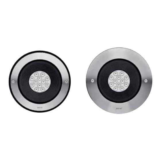
Inground luminaire
Hide thumbs
Also See for ETC330-FS:
Advertisement
Quick Links
Do not open during installation
This product is factory-sealed.
Refer to the instructions contained in this
document for details.
Surge Protection
This product features built-in surge protection circuitry in compliance with
applicable standards.
For comprehensive protection of a luminaire installation against lightning and
electrical surges, it is essential to cover mains supply and data input lines at
the distribution board level, by using respective primary (Type 1) and secondary
(Type 2) surge arrestors in compliance with EN61643-11/IEC61643-1.
Warning
Ensure that all required surge protection measures are in place and activated
prior to luminaire installation. Also, disconnect luminaires before operating
high-power devices such as, for example, electrical arc welders.
WE-EF LEUCHTEN
Installation and Maintenance
Instructions
Inground Luminaire
ETC330-FS
EVC330-FS
ETC340-FS
EVC340-FS
ETC330-FS CC
EVC330-FS CC
ETC340-FS CC
EVC340-FS CC
ETC330-FS TW
EVC330-FS TW
ETC340-FS TW
EVC340-FS TW
Advertisement

Related Manuals for WE-EF ETC330-FS


Summary of Contents for WE-EF ETC330-FS
- Page 1 WE-EF LEUCHTEN Installation and Maintenance Instructions Inground Luminaire ETC330-FS EVC330-FS ETC340-FS EVC340-FS ETC330-FS CC EVC330-FS CC ETC340-FS CC EVC340-FS CC ETC330-FS TW EVC330-FS TW ETC340-FS TW EVC340-FS TW Do not open during installation Surge Protection This product is factory-sealed. This product features built-in surge protection circuitry in compliance with Refer to the instructions contained in this applicable standards.
- Page 2 Inground Luminaire ETC330-FS EVC330-FS ETC330-FS CC* EVC330-FS CC* ETC330-FS TW EVC330-FS TW ETC340-FS EVC340-FS ETC340-FS CC* EVC340-FS CC* ETC340-FS TW EVC340-FS TW IP67, Class I, ta = 40°C Accessories: DMX Wireless* for ETC/EVC330-FS CC 430-0018 0.14 – 2.5 mm ø 5.5 – 12 mm...
-
Page 3: Maintenance
Light Source Maintenance Apart from cleaning the product’s exterior surfaces, no special maintenance work is required. Do not use high-pressure cleaners. In case of component failure due to abnormal circumstances or at end of life, replacement must be carried out Warning: Do not open luminaire while mains supply is switched on. -
Page 4: Installation Methods
Installation Installation Methods The product must be installed and maintained by a Attention: The luminaire is factory-sealed and does not need to be opened during installation. building/construction and/or electrical regulations and relevant legislation. For proper installation, use the supplied installation blockout. - Page 5 Phase One Blockout Installation Procedure 1) Ensure a suitable recess. 2) Select appropriate installation blockout holes S for mains supply cable(s) O and data cable(s) if necessary. 3) Set mounting ring B/M in position. Arrow R on mounting ring M is pointed towards the object to be illuminated (wall, tree, column).
- Page 6 Phase Two Luminaire Installation and Electrical Connection 5) Switch off mains electrical supply. 6) Check that rating shown on luminaire label conforms with mains electrical supply. 03/17 IP67 ETC330-FS 220-240V/60/Hz, 1-10V 185-XXXX SOE XXXXXXX LED 4000K 12W item no. XXX (example)
- Page 7 9) Loosen countersunk screws C (do not turn out). Insert mounting lever L between head of countersunk screws C and cover lens. 10) Set cables and sealable junction box J 11) Place housing A into installation blockout/ inside installation blockout/mounting ring mounting ring assembly B/M while aligning assembly B/M.
- Page 8 12) Remove lever L and tighten countersunk screws C 'hand-tight'.
- Page 9 Tel +1 724 742 0030 Fax +41 22 752 49 74 Fax +1 724 742 0035 info.switzerland@we-ef.com info.usa@we-ef.com WE-EF LIGHTING United Kingdom Tel +44 844 880 5346 Fax +44 844 880 5347 info.uk@we-ef.com TO9192W0919 © WE-EF 2019 subject to change.
Need help?
Do you have a question about the ETC330-FS and is the answer not in the manual?
Questions and answers