Sign In
Upload
Manuals
Brands
Infineon Manuals
Microcontrollers
DriveCard XMC4400 V1
Infineon DriveCard XMC4400 V1 Manuals
Manuals and User Guides for Infineon DriveCard XMC4400 V1. We have
1
Infineon DriveCard XMC4400 V1 manual available for free PDF download: Board User's Manual
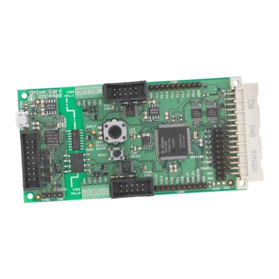
Infineon DriveCard XMC4400 V1 Board User's Manual (29 pages)
Motor Control Application Kit For XMC4000 Family
Brand:
Infineon
| Category:
Microcontrollers
| Size: 1.29 MB
Table of Contents
Table of Contents
4
1 Overview
7
Key Features
7
Block Diagram
8
Figure 1 Block Diagram of KIT_XMC4400_DC_V1
8
2 Hardware Description
9
Power Supply
9
Figure 2 XMC4400 Drive Card (KIT_XMC4400_DC_V1)
9
Table 1 Power Status Led"S
9
Figure 3 Power Supply Concept and Powering Options
10
Figure 4 Block Diagram of Power Supply Concept
10
Reset
11
Clock Generation
11
Debug Interface
11
Figure 5 Reset Button
11
Figure 6 Clock Generation
11
On-Board USB Debugger
12
Figure 7 Installation of Serial Port Driver
12
Figure 8 On-Board USB Debugger
12
Infineon Debug Connector (16-Pin)
13
Figure 9 Infineon Debug Connector (16-Pin)
13
CAN Interface (X402)
14
Potentiometer and User Leds
14
Figure 10 Isolated CAN Interface with Termimation
14
Figure 11 Potentiometer and Leds
14
Table 2 Potentiometer
14
Multifeedback Connectors
15
Figure 12 Multifeedback Interface Connectors
15
Table 3 Multifeedback Interface Connector X201 and X202
15
Hall Sensor and Encoder Connectors
16
Figure 13 Hall Sensor and Encoder Connectors
16
Figure 14 Hall Sensor and Encoder Interface Circuitry
16
Table 4 HALL Sensor and Encoder Interfaces
17
Power Board Connector
18
Level Shifters for Analog Signals
18
Figure 16 Power Board Connector
18
Figure 17 Buffered Level Shifter for High Impedance Analog Signals
18
Table 5 Power Board Connector
19
Table 6 Use Cases of PWM Signals
20
3 Production Data
21
Schematics
21
Figure 18 XMC4400 MCU, Power Supply, Multifeedback Interface
22
Figure 19 Hall Sensor and Encoder Interfaces, Power Board Connector
23
Figure 20 Isolated On-Board Debugger and CAN Interface
24
Component Placement
25
Figure 21 Component Placement
25
Bill of Material (BOM)
26
Table 7 BOM of KIT_XMC4400_DC_V1 Board
26
Advertisement
Advertisement
Related Products
Infineon XMC4500 series
Infineon XMC4000 series
Infineon XMC4200
Infineon XMC4400
Infineon XMC4500 SDRAM
Infineon XMC4700
Infineon XMC Series
Infineon XMC7000 Series
Infineon XMC7100 Series
Infineon XMC1100
Infineon Categories
Motherboard
Microcontrollers
Computer Hardware
Control Unit
Controller
More Infineon Manuals
Login
Sign In
OR
Sign in with Facebook
Sign in with Google
Upload manual
Upload from disk
Upload from URL