Summarization of Contents
Introduction
Overview
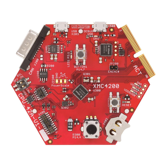
Provides a general introduction to the CPU board and its capabilities.
Key Features
Lists the main hardware features and specifications of the CPU board.
Hardware Description
Power Supply
Details how the CPU board is powered, including USB and external sources.
Reset
Explains the reset functionality, including the reset button and LED indicator.
Clock Generation
Describes the clock sources and circuits used by the microcontroller.
Boot Option
Details the boot configuration options set via the dip switch.
Debug Interface
Covers the different methods supported for debugging the CPU board.
On-board USB Debugger
Explains the functionality and setup of the integrated USB debugger.
Cortex Debug Connector (10-pin)
Details the pinout and function of the 10-pin Cortex debug connector.
Cortex Debug+ETM Connector (20-pin)
Details the pinout and function of the 20-pin Cortex debug+ETM connector.
Serial Flash Memory
Describes the onboard serial flash memory and its SPI interface.
SDRAM
Details the synchronous dynamic RAM interface and configuration.
USB
Explains the USB interface capabilities: host, device, and OTG modes.
RTC
Covers the Real-Time Clock functionality and power domains.
User LEDs and User Button
Describes the onboard LEDs and user buttons and their connections.
Potentiometer
Details the potentiometer and its connection to the ADC input.
Satellite Connectors
Introduces the three satellite connectors for expansion.
COM Connector
Details the COM satellite connector's pinout and functions.
HMI Connector
Details the HMI satellite connector's pinout and functions.
ACT Satellite Connector
Details the ACT satellite connector's pinout and functions.
Production Data
Schematics
Lists the available schematics for the CPU board components.
Bill of Material (BOM)
Provides a detailed list of components used on the CPU board.


Need help?
Do you have a question about the XMC4500 SDRAM and is the answer not in the manual?
Questions and answers