Table of Contents
Advertisement
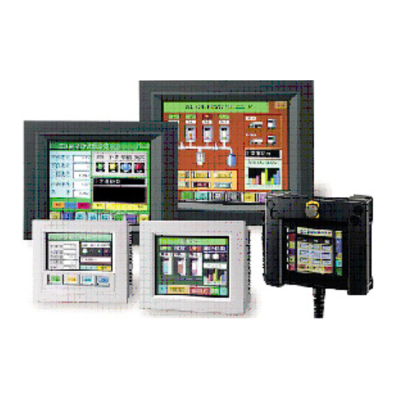
Let's Connect an
Operator Interface to a
Barcode Reader!
Practical Guide for Sample Program of the
Barcode Reader Connection
This text introduces an example of a system that imports barcode data captured by a barcode reader
into an operator interface, displaying imported data on the operator interface, and determining
OK/NG judgments.
Please open the O/I data "BCR2_BASIC_EN" and "BCR_ADVANCE_EN" stored in this Demo
version CD with the associated application software. Then, check the details of each program and
settings of this sample program while referring to the descriptions in this text. Display and entry area
of barcode number STORED/ COMPARE DATA Display and entry area of barcode number
STORED/ COMPARE DATA
Note that the data of O/I stored on this Trial Version CD is a sample and that proper operation is not
guaranteed by IDEC IZUMI.
Note: Direct connection of a barcode reader to an operator interface is supported by O/I Screen
Creation Software "WindO/I-NV2" Ver. 2.7 and later.
Publication date
Version
Revision history
Feb. 1, 2005
Ver.1.00
First edition
1
Advertisement
Table of Contents

Related Manuals for IDEC HG2F-SS22VF

Summary of Contents for IDEC HG2F-SS22VF
- Page 1 Note that the data of O/I stored on this Trial Version CD is a sample and that proper operation is not guaranteed by IDEC IZUMI. Note: Direct connection of a barcode reader to an operator interface is supported by O/I Screen Creation Software “WindO/I-NV2”...
-
Page 2: Table Of Contents
Table of Contents 1. System Configurations Required hardware and application software …………….………………… ……………………………………………………. System configurations 2. Operating Procedures ……………………………………….….………………… Program screen ……………………………………………………. Reading barcode data ……………………………………….. Registering scanned barcode data ………………………… Displaying “OK” or “NG” when reading barcodes ……………………………………. Clearing the registered barcode data 3. -
Page 3: System Configurations
Datalogic’s CCD Scanner for 1-D Codes Barcode Reader CAB-320 Datalogic’s RS 232C Interface Cable PG5/110V Datalogic’s AC Adapter 1-2 System configuration Operator Interface Model: HG2F-SS22VF Computer Link Cable Model: FC2A-KC4C Connect the mini-DIN8 connector on the rear face to SERIAL2 (Round pin). Programming Software User Communication Cable “WindO/I-NV2”... -
Page 4: Operating Procedures
2. Operating Procedures This application software operates as follows: Register one type of 13-digit barcode data to the operator interface, an “OK” is displayed on the screen when the data scanned with the barcode reader matches the Stored Data. Otherwise, “NG” is displayed. The following are the details of the operating procedure. -
Page 5: Reading Barcode Data
2. Operating Procedures 2-2 Reading barcode data Press the button of the barcode reader connected to the operator interface to scan a 13-digit barcode. On the HG2F screen, the scanned barcode data is displayed in the READ DATA area. The”NG” lamp illuminates because STORED DATA has not been registered. -
Page 6: Displaying "Ok" Or "Ng" When Reading Barcodes
2. Operating Procedures 2-4 Displaying “OK” or “NG” when reading barcodes The “OK” lamp illuminates when the READ DATA matches the STORED DATA. The “NG” lamp illuminates when the READ DATA does not match the STORED DATA. 2-5 Clearing the registered barcode data Pressing the CLEAR DATA button will clear the barcode data registered as the STORED DATA. -
Page 7: User Communication Settings
3. User Communication Settings The [User Communication] function enables direct communications between the HG series operator interface and a barcode reader via an RS-232C cable. This application introduces the settings of an HG2F program, configured by WindO/I-NV2, for reading barcode data with a barcode reader GRYPHON D100 (Izumi Datalogic Co.). - Page 8 3. User Communication Settings Select the protocol to be used with the interface you have selected in the previous step. Select “User Communication 1” for the Protocol options in the “Interface settings” field, because the User Communication function is used for connection to the barcode reader. Selecting “User Communication 1”...
-
Page 9: Setting The User Communication Settings
3. User Communication Settings 3-2 Setting the User Communication settings Select “User Communication 1” and then click the [Select] button. When the “Protocol Library” dialog box appears, select “Barcode-Reader 1” in the Protocol field, and then click the [OK] button. -
Page 10: Protocol Of Barcode Reader
3. User Communication Settings Check that “Barcode-Reader 1” is entered in the “Protocol Name” column for the User Communication in the “Set Protocol” field. Selecting “No. 1” in the “Protocol” field in the dialog box will display the details of the command in the “Command”... -
Page 11: Device Used With The Barcode Reader Protocol
3. User Communication Settings 3-4 Device used with the barcode reader protocol The data scanned by the barcode reader and the reception status are stored in the following devices. Data reception is performed constantly. Barcode-Reader1 Device Description LDR 8000-0 Reception completion bit (Turns on when data reception is complete. <Automatically turned off.>) Reception status (Bit 0 to 14: reception data error under ON status;... -
Page 12: Description Of The Program
4. Description of the Program 4-1 Device allocations of the program screen (1) Display area of (3) STORE button used for registered barcode data registering barcode data (2) Display area of (4) CLEAR DATA button for scanned barcode data clearing the barcode registration (6) NG lamp (5) OK lamp... -
Page 13: Displaying The Barcode Data
4. Description of the Program 4-2 Displaying barcode data “Message Display” is a screen that is available with the operator interface is used for displaying the barcode data. A Message Display is capable of displaying text data (ASCII or Shift-JIS code) in the operator interface and PLC or other devices. -
Page 14: Creating The Store Button For The Barcode Data
4. Description of the Program 4-3 Creating the STORE button for the barcode data A “Word Button” is available with the operator interface is used for creating the STORE button for the barcode data. In this example, use the Move function of the Word Button to copy the value of the READ DATA to STORED DATA. -
Page 15: Creating The Clear Data Button For The Barcode Data
4. Description of the Program 4-4 Creating the CLEAR DATA button for the barcode data A “Word Button” is available with the operator interface and is used for creating the CLEAR DATA button for the barcode data. In this example, use the Set function of the Word Button to copy “0” to STORED DATA. -
Page 16: Judging The Match Or Mismatch Of Barcode Data
4. Description of the Program 4-5 Judging the match or mismatch of barcode data The comparison between the READ DATA and STORED DATA is performed using the following procedures. (1) The READ DATA (LDR8010 to 8016) is compared to the STORED DATA (LDR100 to 106) successively word by word. - Page 17 4. Description of the Program (2) When the “Bit Write Command” dialog box is displayed, configure the Trigger Condition settings first. (3) Select “While satisfying the condition” in the Trigger Type field. (4) Click the […] button on the right of the Condition field to open the “Trigger Condition Settings”...
-
Page 18: Judging The Barcode Data Matching
4. Description of the Program 4-7 Judging the barcode data matching When the READ DATA matches the STORED DATA completely, LDR100-0 to LDR100-6 are turned on and the value of LDR100 becomes “127”. Configure the setting so that the [OK] lamp is turned on under this condition. -
Page 19: Advanced Program For Barcode Comparison
5. Advanced Program for Barcode Comparison This application program compares the scanned barcode with 50 types of pre-registered barcodes, (up to 20 digits, alphanumeric characters can be used), and then displays “OK” when the data matches or “NG” when the data does not match. After configuring the barcode protocol using User Communications, import the Advanced Barcode Comparison Application Program to your screen with the “Import Screens (*)”... -
Page 20: Entering The Barcode Number For Registration And Verification
5. Advanced Program for Barcode Comparison 5-2 Entering the barcode number for registration and verification Before registering a barcode, enter the “Bar Code Number” you want to register. Press the display area of the Bar Code Number on the screen. When a numeric keypad is displayed, enter the number with which you want to register (verify) the barcode data. -
Page 21: Displaying "Ok" Or "Ng" Upon Reading Barcodes
5. Advanced Program for Barcode Comparison 5-5 Displaying “OK” or “NG” upon reading barcodes The [OK] lamp illuminates when the READ DATA matches the barcode data designated for verification. When the data does not match, the [NG] lamp illuminates. 5-6 Modifying the barcode data for verification Pressing the display area of STORED/COMPARE Data will display character keys. -
Page 22: Device Setting In The Sample Program
5. Advanced Program for Barcode Comparison 5-7 Device setting in the example program In this example program, various data items are allocated to the following devices. The “LM”, “LDR”, and “LKR” in the table below are the internal devices of the operator interface. (LM: Internal relay of operator interface, LDR: Register of operator interface, LKR: Keep register of operator interface) Device... -
Page 23: Storage Location Of The Registration Number And Barcode Data
5. Advanced Program for Barcode Comparison 5-8 Storage location of the registration number and barcode data The following comparative table lists the storage locations of the barcode number and data in the operator interface when registering and verifying the data. LKR is the storage location of data for data-retention within the operator interface, and it can retain data for approximately one month when the internal battery of the operator interface is on a full charge. -
Page 24: Using The Results Of Barcode Detections
5. Advanced Program for Barcode Comparison 5-9 Using the results of barcode detections This section describes how to develop the Advanced Barcode Comparison Application Program to actual comparative outputs of your PLC. (Make sure that the barcode reader and HG series are connected as described in “1 System Configurations”.) (1) Configure the User Communication settings up to the condition described in “3. - Page 25 For any inquires, please contact IDEC Customer Support. Hong Kong United States IDEC IZUMI (H.K.) Co., Ltd. IDEC Corporation Tel: +852-2803-8989 Tel: +1-408-747-0550 / (800) 262-IDEC(4332) Fax: +852-2565-0171 Fax: +1-408-744-9055 / (800) 635-6246 E-mail: idec@idechk.com E-mail: opencontact@idec.com China Canada IDEC IZUMI (Shanghai) Co., Ltd.
Need help?
Do you have a question about the HG2F-SS22VF and is the answer not in the manual?
Questions and answers