Advertisement
Quick Links
STOP&GO connected kit
and automatic resetting
4 149 54
Connected STOP&GO (remote control
Pack
Cat.Nos
resetting)
For remotely switching (via a smartphone or tablet)
1 module per pole RCCBs and RCBOs up to 63 A.
Examples of use:
- In the event of unwanted tripping (generated
by temporarily electrical disturbances or other
external events) the Connected STOP&GO will do an
automatic checking of the installation.
If no permanent fault is detected: it will send a
message on the smartphone or tablet of the user
in order to get an authorization to switch on the
associated device.
In case of permanent fault: the user will be informed
about it without having the possibility to remotely
switch on the power.
Needs a permanent internet connection via a Wi-FI
modem/router (powered by an UPS) in order to send
messages to the user and allow him to remotely
control the circuit.
- In a normal situation, to remotely switch ON a
circuit (like the electrical heating in a holiday house).
Can take one control auxiliary and one signalling
auxiliary. The signalling auxiliary must be placed
between the STOP&GO and the control auxiliary.
No tool required for assembling.
Kit comprising:
- 1 Connected STOP&GO (non-automatic)
- 1 IP gateway (Wi-Fi connection)
- 1 power supply module, input voltage 230 V A /
output voltage 12 V =
- 2 communication cables
Control voltage
1
4 149 54
230 VA
STOP&GO automatic resetting
For automatic resetting of 1 module per pole RCCBs
and RCBOs up to 63 A
STOP&GO is used in the event of unwanted tripping
generated by temporarily electrical disturbances or
other external events. Can take one control auxiliary
and one signalling auxiliary. The signalling auxiliary
must be placed between the STOP&GO and the
control auxiliary. No tool required for assembling
Automatic resetting function
Control voltage
1
4 062 88
230 VA
Automatic resetting + periodic self-test function
1
4 062 89
230 VA
Voltage surge protectors
p. 66-70
Keor UPS
p. 678
4 062 88
No. of modules
4
No. of modules
2
2
Manual supply invertor DX
and accessories
4 063 14
Manual supply invertor (MSI)
Pack
Cat.Nos
For manually switching between the mains and an
alternative power supply.
Allow to restore power on pre-designated and/or
critical circuits in case of a power failure of the main
supply.
For DX
MCBs and remote trip isolating switches
3
Installation principle - see e-catalogue
1
4 063 14 For 2P 2-module devices
1
4 063 15 For 3P 3-module devices
4 063 16 For 4P 4-module devices
1
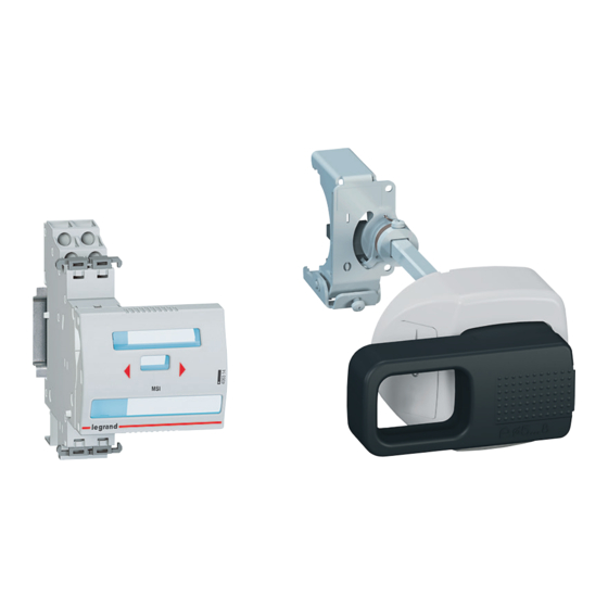
Front external rotary handles
Allow the manual control (open/close) of a modular
device without opening the enclosure
For all DX³, TX
Supplied with bracket, connection rod, handle,
self-adhesive drilling template and connection
accessories
Installation principle - see e-catalogue
1
4 063 19 Black handle
1
4 063 20 Yellow and red handle
Wiring management accessories
Insulating shields
For 1 module per pole MCBs
4 063 05 For separation between the terminals
1
of the MCB, when using high cross
section cables
Spacing unit with feedthrough
10
4 063 07 0.5 module
Allows cables to run between two
modular devices and creates an air
channel in order to limit temperature rise
Terminals for aluminium cables
1
4 063 10 For 1 and 1.5 module/pole MCBs up to 63 A
1
4 063 11 For 1.5 module/pole MCBs and remote
trip isolating switches from 80 A to 125 A
Safety and maintenance accessories
Sealable screw covers
4 063 04 For 1 module per pole MCBs (set of 4)
2
1
4 063 12 For 1.5 module per pole MCBs (set of 4)
Terminal shield
1
4 063 06 For 1.5 module/pole MCBs (set of 2)
Padlocking
To lock the handle of a modular device during
maintenance
1
0 227 97 Large padlock, Ø6 mm, 50 mm length
Supplied with two keys and labels
3
4 063 13 Small padlock, Ø5 mm
2
4 063 03 Support for one padlock (for small or large model)
For locking the handle of the modular devices
(MCBs, RCCBs, RCBOs or isolating switches) in
OFF position
3
4 063 19
and RX
devices from 2P upwards
3
3
65
Advertisement


Need help?
Do you have a question about the DX3 and is the answer not in the manual?
Questions and answers