Table of Contents
Advertisement
Quick Links
PCE Americas Inc.
PCE Instruments UK Ltd.
711 Commerce Way
Units 12/13
Suite 8
Southpoint Business Park
Jupiter
Ensign way
FL-33458
Hampshire / Southampton
USA
United Kingdom, SO31 4RF
From outside US: +1
From outside UK: +44
Tel: (561) 320-9162
Tel: (0) 2380 98703 0
Fax: (561) 320-9176
Fax: (0) 2380 98703 9
info@pce-americas.com
info@pce-instruments.com
www.pce-instruments.com/english
www.pce-instruments.com
Manual
Automotive Tester PCE-VE 5xx Series
Version 1.1
Date of creation: 15.01.2015
Date of last change: 03.05.2016
Advertisement
Table of Contents

Related Manuals for PCE Instruments PCE-VE 5 Series


Summary of Contents for PCE Instruments PCE-VE 5 Series
- Page 1 PCE Americas Inc. PCE Instruments UK Ltd. 711 Commerce Way Units 12/13 Suite 8 Southpoint Business Park Jupiter Ensign way FL-33458 Hampshire / Southampton United Kingdom, SO31 4RF From outside US: +1 From outside UK: +44 Tel: (561) 320-9162 Tel: (0) 2380 98703 0...
-
Page 2: Table Of Contents
Contents Introduction ......................3 Safety notes ......................4 Specifications ......................5 System description ....................6 Design ........................... 6 Operation modes ........................7 Keys ............................7 Display indications ......................... 8 Handle LED indications ......................8 How to re-charge the battery ....................8 Preparation ...................... -
Page 3: Introduction
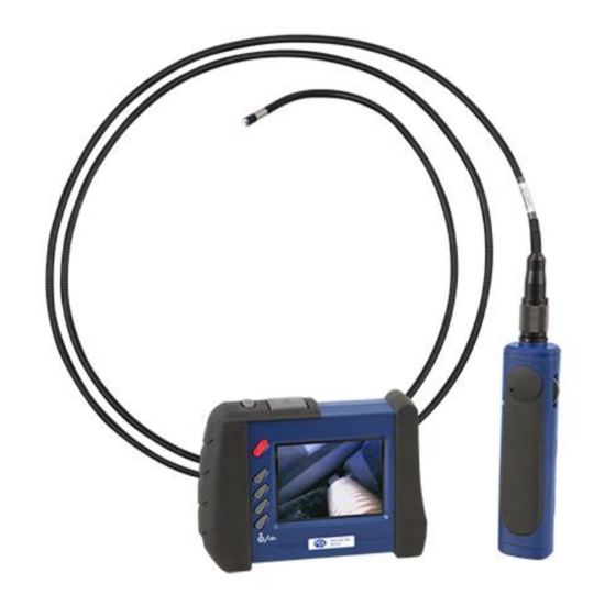
PCE Americas ........................23 Introduction Thank you for purchasing a wireless video endoscope PCE-VE 500 from PCE Instruments. This wireless radio video endoscope with flexible or semi-flexible wire is a professional meter for workshops and for installation work and also other areas where it is necessary to view the interior of machines and installations. -
Page 4: Safety Notes
Please read this manual carefully and completely before you use the device for the first time. The device may only be used by qualified personnel and repaired by PCE Instruments personnel. There is no warranty of damages or injuries caused by non-observance of the manual. -
Page 5: Specifications
Manual Specifications Technical specifications Flexible cable length 2000 mm Cable type flexible Cable diameter 5.5 mm Field of view / angle horizontal 46º; vertical 34º; diagonal 56º Image sensor CMOS Minimum illumination 0 lx Size of the display 3.5" LCD Pixels 640 x 480 Video output system... -
Page 6: System Description
Manual System description Design... -
Page 7: Operation Modes
Manual Operation modes This device has 3 operation modes which are Preview, Browse and Menu mode. Preview mode Preview mode will be activated as soon as the handle bar is powered on. When you target the camera tip at an object, the image will be displayed at the same time. -
Page 8: Display Indications
Manual Display indications Icon Meaning Memory capacity of SD card Charging level 2 x zoom active Mirror effect active Handle LED indications LED light colour Battery status Note Green In use Working with full battery Dark red Low battery Please recharge the battery when the dark red light appears during operation Orange... -
Page 9: To Adjust The Channel
Manual To adjust the channel The handle bar and the LCD unit must be on the same channel during wireless transmission. Adjust the channel by using a small slotted screwdriver, following the direction of the arrows as shown below. Please refer to the following chart to select a suitable channel. Channel Arrow indication Frequency... -
Page 10: Operation
Manual Operation Power on/off button for 3 … 5 seconds until you see the icons below To turn on the LCD unit, push and hold the on your monitor: SD card memory capacity Battery capacity To switch from wireless to direct control 1. -
Page 11: To Delete A Picture Or Video (In Browse Mode Only)
Manual To delete a picture or video (in Browse mode only) 1. Enter Browse mode and find the picture or video you wish to delete by pushing the buttons. 2. Push 3. Push OK/MENU to delete the selected file or push ESC to cancel. Zoom-In Push the ESC button once. -
Page 12: To Delete All Files
Manual To delete all files After selecting “DELETE ALL FILES” by pushing the buttons, press OK/MENU. Select “yes” or “no” and confirm with the OK/MENU key. Video output – to activate the AV output 1. Plug one end of the included AV cord into the AV socket located on the right-hand side of the LCD unit and plug the other end of the AV cord into the “AV in”... -
Page 13: Tv System
Do not use any corrosive agents for cleaning (e. g. alcohol). Do not disassemble the device as this can cause damage and electric shocks. Only use components and accessories recommended by PCE Instruments. Unapproved components and accessories can cause damage. - Page 14 Manual Do not apply force to the end of the cable and do not bend it. This can deteriorate your vision and even damage the probe. When you roll up the cable, the inner diameter must be at least 15 cm. ...
-
Page 15: Technical Specifications
Manual Make sure that the camera does not get in contact with the following liquids: lead-free petrol, diesel oil, machine oil, brake fluid, transmission oil and water. Do not screw the accessories on too tightly. Only screw it slightly until it is fixed. ... -
Page 16: System Description
Manual System description 1. Probe: to guide the camera 2. Camera head: for illumination and capturing 3. Assembly ring: to attach accessories 4. Protection ring: to protect the thread 5. Red cap: protects the camera when not in use 6. Boost key: for better illumination in dark environments 7. - Page 17 Manual Attachment of the accessories Mirror Step 1: Unscrew the thread protection ring. Step 2: Screw the assembly ring down to the bottom. Step 3: Screw the mirror attachment onto the thread until the thread is completely covered. Step 4: Align the lateral LED opening of the mirror attachment in a way that the LEDs are uncovered. Step 5: Turn the assembly ring upwards in order to fix the mirror attachment.
-
Page 18: Instructions
Manual Magnetic hook Step 1: Turn the assembly ring down to the bottom. Step 2: Screw the magnetic hook on until it snaps in. Climbing ball Step 1: Remove the assembly ring. Step 2: Screw the climbing ball on until it snaps in. Instructions Boost key Use this key in a dark environment. - Page 19 Manual Rotation key You can use this key to turn the image by 90 ° four times, for instance, when trying to read an inscription completely. Light key When using the mirror attachment, this key improves the vision which will not be impeded by particles, dust, etc.
-
Page 20: Articulating Camera Cable (Optional)
Manual Articulating camera cable (optional) Safety notes In addition to the general safety notes of the PCE-VE 500 series, please mind the following safety notes to prevent damage and injuries when using the pivoting camera head. Do not bend the pivoting camera head by hand. Only use the rotary switch to adjust the angle. ... -
Page 21: System Description
Manual System description Camera cable Camera head Gooseneck Operating unit Rotary switch for gooseneck Connecting cable Connector Locking lever Getting started 1. Connect the connecting cable to the display unit of the endoscope and screw it tightly. Make sure that the indication on the connector is on the upper side. -
Page 22: Operation
Manual Operation 1. By using the rotary switch, you can pivot the camera head. Turn the switch in a clockwise motion to pivot the camera head to the right or in a counter-clockwise motion to pivot the camera head to the left. -
Page 23: 10 Disposal
In order to comply with the EU directive 2012/19/EU we take our devices back. We either re-use them or give them to a recycling company which disposes of the devices in line with law. If you have any questions, please contact PCE Instruments. 11 Contact If you have any questions about our range of products or measuring instruments please contact PCE Instruments.
Need help?
Do you have a question about the PCE-VE 5 Series and is the answer not in the manual?
Questions and answers