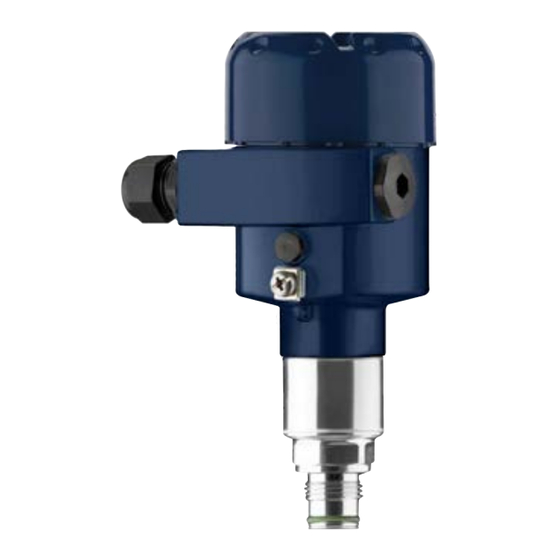
WIKA IPT-2 Series Operating Instructions Manual
Process pressure transmitter
Hide thumbs
Also See for IPT-2 Series:
- Safety manual (20 pages) ,
- Operating instructions manual (80 pages)

Related Manuals for WIKA IPT-2 Series


Summary of Contents for WIKA IPT-2 Series
- Page 1 Operating Instructions Process pressure transmitter IPT-2x Slave for electronic differential pressure Metallic sensor Process pressure transmitter IPT-2x...
-
Page 2: Table Of Contents
Exchange process module on version IP68 (25 bar) ............42 Exchanging the electronics module ................43 Instrument repair ......................43 Dismount..........................45 Dismounting steps......................45 Disposal ......................... 45 Supplement ..........................46 Technical data ........................ 46 WIKA Operating Instructions - Process pressure transmitter IPT-2x... - Page 3 Take note of the Ex specific safety instructions for Ex applications. These instructions are attached as documents to each instrument with Ex approval and are part of the operating instructions. Editing status: 2020-05-12 WIKA Operating Instructions - Process pressure transmitter IPT-2x...
-
Page 4: About This Document
The dot set in front indicates a list with no implied sequence. Sequence of actions Numbers set in front indicate successive steps in a procedure. Battery disposal This symbol indicates special information about the disposal of bat- teries and accumulators. WIKA Operating Instructions - Process pressure transmitter IPT-2x... -
Page 5: For Your Safety
EU conformity The device fulfils the legal requirements of the applicable EU direc- tives. By affixing the CE marking, we confirm the conformity of the instrument with these directives. WIKA Operating Instructions - Process pressure transmitter IPT-2x... -
Page 6: Installation And Operation In The Usa And Canada
National Electrical Code (ANSI/NFPA 70). Installations in Canada shall comply with the relevant requirements of the Canadian Electrical Code. Exception: Versions with measuring ranges from 250 bar. These are subject of the EU Pressure Device Directive. WIKA Operating Instructions - Process pressure transmitter IPT-2x... -
Page 7: Product Description
On the type plate of the electronics module • In the adjustment menu under "Info" Type label The type label contains the most important data for identification and use of the instrument: WIKA Operating Instructions - Process pressure transmitter IPT-2x... -
Page 8: Principle Of Operation
Flow • Differential pressure • Density • Interface • Level, density-compensated Electronic differential The IPT-2x slave sensor is combined with a sensor from the instru- pressure ment series for electronic differential pressure measurement. WIKA Operating Instructions - Process pressure transmitter IPT-2x... - Page 9 The process pressure causes a resistance change which is converted into a corresponding output signal and output as measured value. Piezoresistive sensor element Measuring ranges up to 40 bar: piezoresistive sensor element with internal transmission liquid is used. WIKA Operating Instructions - Process pressure transmitter IPT-2x...
- Page 10 With small measuring ranges ≤ 400 mbar or higher temperature ranges, the ceramic/metallic measuring cell is the measuring unit. It consists of the ceramic-capacitive measuring cell and a special, temperature-compensated chemical seal system. WIKA Operating Instructions - Process pressure transmitter IPT-2x...
-
Page 11: Supplementary Cleaning Procedures
Caution: The IPT-2x in this version may not be used in oxygen applications. For this purpose, instruments are available in the special version "Oil, grease and silicone-free for oxygen applications". WIKA Operating Instructions - Process pressure transmitter IPT-2x... -
Page 12: Packaging, Transport And Storage
Technical data - Ambient conditions" • Relative humidity 20 … 85 % With instrument weights of more than 18 kg (39.68 lbs) suitable and Lifting and carrying approved equipment must be used for lifting and carrying. WIKA Operating Instructions - Process pressure transmitter IPT-2x... -
Page 13: Mounting
Screwing in Devices with threaded fitting are screwed into the process fitting with a suitable wrench via the hexagon. See chapter "Dimensions" for wrench size. WIKA Operating Instructions - Process pressure transmitter IPT-2x... - Page 14 Make sure that the upper temperature limits stated in chapter "Technical data" for the environment of the electronics hous- ing and connection cable are not exceeded. Fig. 6: Temperature ranges Process temperature Ambient temperature WIKA Operating Instructions - Process pressure transmitter IPT-2x...
-
Page 15: Ventilation And Pressure Compensation
→ Filter element - Position Turn the metal ring in such a way that the filter element points Ex-d version downward after installation of the instrument. This provides better protection against buildup. WIKA Operating Instructions - Process pressure transmitter IPT-2x... - Page 16 Filter element - Position IP69K version Fig. 10: Position of the filter element - IP69K version Filter element Instruments with absolute pressure have a blind plug mounted instead of the filter element. WIKA Operating Instructions - Process pressure transmitter IPT-2x...
-
Page 17: Combination Master - Slave
Nominal measuring range Master: 0.4 bar Nominal measuring range Slave: 0.4 bar Turn Down: 0.4 bar /0.049 bar = 8.2 : 1 Example - orifice in Data pipeline Application: Differential pressure measurement Medium: Gas Static pressure: 0.8 bar WIKA Operating Instructions - Process pressure transmitter IPT-2x... -
Page 18: Level Measurement
Mount the master sensor so that it is protected against pressure shocks from the stirrer • Mount the slave sensor above the max. level Fig. 11: Measurement setup, level measurement in pressurized vessel IPT-2x IPT-2x, slave sensor WIKA Operating Instructions - Process pressure transmitter IPT-2x... -
Page 19: 4.5 Differential Pressure Measurement
The mounting distance h of the two sensors should be at least 10 %, better 20 %, of the final value of the sensor measuring range. A bigger distance increases the accuracy of the interface measurement. WIKA Operating Instructions - Process pressure transmitter IPT-2x... -
Page 20: Density Measurement
The master/slave combination is suitable for density measurement. Requirements for a functioning measurement are: • Vessel with changing level • Distance between the measurement points as large as possible • Level always above the upper measuring point WIKA Operating Instructions - Process pressure transmitter IPT-2x... -
Page 21: Density-Compensated Level Measurement
Mount the master sensor below the min. level • Mount the slave sensor above the master sensor • Mount both sensors away from the filling stream and emptying and protected against pressure shocks from the stirrer WIKA Operating Instructions - Process pressure transmitter IPT-2x... - Page 22 The density-compensated level measurement is only possible in open, i.e. unpressurized vessels. WIKA Operating Instructions - Process pressure transmitter IPT-2x...
-
Page 23: External Housing
4 Mounting External housing Configuration Fig. 16: Configuration, process module, external housing Pipeline Process module Connection cable process assembly - External housing External housing Signal cable WIKA Operating Instructions - Process pressure transmitter IPT-2x... -
Page 24: Connecting To Power Supply
The connection to the Master sensor is carried out through spring- loaded terminals in the respective housing. For this, use the supplied, confectioned cable. Solid cores as well as flexible cores with cable end sleeves are inserted directly into the terminal openings. WIKA Operating Instructions - Process pressure transmitter IPT-2x... - Page 25 9. Unscrew the blind plug on the Master, screw in the supplied cable gland 10. Connection cable to Master, see steps 3 to 8 11. Screw the housing lid back on WIKA Operating Instructions - Process pressure transmitter IPT-2x...
-
Page 26: Single Chamber Housing
Fig. 19: IPT-2x in IP68 version 25 bar with axial cable outlet, external housing Transmitter Connection cable External housing Connect shielding here. Connect ground terminal on the outside of the hous- ing to ground as prescribed. The two terminals are galvanically connected. WIKA Operating Instructions - Process pressure transmitter IPT-2x... - Page 27 Cable gland for voltage supply Cable gland for connection cable, transmitter Terminal compartment, housing socket 1 2 3 4 Fig. 21: Connection of the process component in the housing base Yellow White Black Shielding Breather capillaries WIKA Operating Instructions - Process pressure transmitter IPT-2x...
-
Page 28: Connection Example
Terminal 6 Terminal 7 Terminal 7 Terminal 8 Terminal 8 Connect shielding here. Connect ground terminal on the outside of the hous- ing to ground as prescribed. The two terminals are galvanically connected. WIKA Operating Instructions - Process pressure transmitter IPT-2x... -
Page 29: Set Up With The Display And Adjustment Module
6.1.1 Setup Application In this menu item you activate/deactivate the slave sensor for elec- tronic differential pressure and select the application. WIKA Operating Instructions - Process pressure transmitter IPT-2x... - Page 30 There are the following possibilities for a position correction with a master/slave combination • Automatic correction for both sensors • Manual correction for the Master (differential pressure) • Manual correction for the Slave (static pressure) WIKA Operating Instructions - Process pressure transmitter IPT-2x...
- Page 31 With the application "Level", the hydrostatic pressure, e.g. with full and empty vessel, is entered for adjustment. A superimposed pres- sure is detected by the slave sensor and automatically compensated. See the following example: WIKA Operating Instructions - Process pressure transmitter IPT-2x...
- Page 32 Now select with [->] the menu item "Adjustment", then "Min. adjustment" and confirm with [OK]. 2. Edit the percentage value with [OK] and set the cursor to the requested position with [->]. WIKA Operating Instructions - Process pressure transmitter IPT-2x...
- Page 33 The maximum negative pressure must then be entered for the min. adjustment. For linearization, select "bidirectional" or "bidirectional-extracted by root" accordingly, see menu item "Liner- arization". The min. adjustment is finished. WIKA Operating Instructions - Process pressure transmitter IPT-2x...
- Page 34 1. Select with [->] the menu item Span adjustment and confirm with [OK]. 2. Edit the mbar value with [OK] and set the cursor to the requested position with [->]. WIKA Operating Instructions - Process pressure transmitter IPT-2x...
- Page 35 2. Edit the percentage value with [OK] and set the cursor to the requested position with [->]. 3. Set the requested percentage value with [+] and save with [OK]. The cursor jumps now to the density value. WIKA Operating Instructions - Process pressure transmitter IPT-2x...
- Page 36 2. Edit the percentage value with [OK] and set the cursor to the requested position with [->]. 3. Set the requested percentage value with [+] and save with [OK]. The cursor jumps now to the height value. WIKA Operating Instructions - Process pressure transmitter IPT-2x...
- Page 37 2. Edit the percentage value with [OK] and set the cursor to the requested position with [->]. 3. Set the requested percentage value (e.g. 100 %) with [+] and save with [OK]. The cursor jumps now to the pressure value. WIKA Operating Instructions - Process pressure transmitter IPT-2x...
- Page 38 As input signals, the output values of Transducer Block (TB) can be selected. The device assumes an approximately constant temperature and static pressure and calculates the flow rate from the measured differential pressure using the characteristic curve extracted by root. WIKA Operating Instructions - Process pressure transmitter IPT-2x...
- Page 39 In menu item "Peak value, pressure", both values are displayed. In another window you can carry out a reset of the peak values separately. WIKA Operating Instructions - Process pressure transmitter IPT-2x...
- Page 40 During simulation, the simulated value is output as digital signal. The status message along with the Asset Management function is "Maintenance". Note: Without manual deactivation, the sensor terminates the simulation automatically after 60 minutes. WIKA Operating Instructions - Process pressure transmitter IPT-2x...
- Page 41 Furthermore the adjustment for the volume or mass flow at 0 % or 100 % is carried out. The device automatically adds the flow in the selected unit. With appropriate adjustment and bidirectional linearization, the flow rate is counted both positively and negatively. WIKA Operating Instructions - Process pressure transmitter IPT-2x...
-
Page 42: Diagnosis, Asset Management And Service
Hexagon key wrench, size 2 Caution: The exchange may only be carried out in the complete absence of line voltage. In Ex applications, only a replacement part with appropriate Ex ap- proval may be used. WIKA Operating Instructions - Process pressure transmitter IPT-2x... -
Page 43: Exchanging The Electronics Module
Instrument repair You can find information for a return shipment under "Service" on our local website. If a repair is necessary, please proceed as follows: • Complete one form for each instrument WIKA Operating Instructions - Process pressure transmitter IPT-2x... - Page 44 7 Diagnosis, asset management and service • If necessary, state a contamination • Clean the instrument and pack it damage-proof • Attach the completed form and possibly also a safety data sheet to the instrument WIKA Operating Instructions - Process pressure transmitter IPT-2x...
-
Page 45: Dismount
Pass the instrument directly on to a specialised recycling company and do not use the municipal collecting points. If you have no way to dispose of the old instrument properly, please contact us concerning return and disposal. WIKA Operating Instructions - Process pressure transmitter IPT-2x... -
Page 46: Supplement
Synthetic oil for measuring ranges up to 40 bar, FDA listed for the food processing industry. For measuring ranges up to 100 bar dry measuring cell. Halocarbon oil: Generally in oxygen applications, not with vacuum measuring ranges, not with absolute meas- uring ranges < 1 bar WIKA Operating Instructions - Process pressure transmitter IPT-2x... - Page 47 Max. torque for NPT cable glands and Conduit tubes Ʋ Plastic housing 10 Nm (7.376 lbf ft) Ʋ Aluminium/Stainless steel housing 50 Nm (36.88 lbf ft) Glass with Aluminium and stainless steel precision casting housing WIKA Operating Instructions - Process pressure transmitter IPT-2x...
- Page 48 0 … 10 bar/0 … 1000 kPa 30 bar/3000 kPa 0 bar abs. 0 … 16 bar/0 … 1600 kPa 50 bar/5000 kPa 0 bar abs. Data on overload capability apply for reference temperature. WIKA Operating Instructions - Process pressure transmitter IPT-2x...
- Page 49 Overload capability Maximum pressure Minimum pressure Gauge pressure 0 … +1.5 psig +220 psig -14.5 psig 0 … +5 psig +435 psig -14.5 psig Data on overload capability apply for reference temperature. WIKA Operating Instructions - Process pressure transmitter IPT-2x...
- Page 50 -10 … 100 % Ʋ Level value according to the measuring ranges in m Max. permissible Turn Down Unlimited (recommended 20 : 1) Dynamic behaviour output Dynamic characteristics depending on medium and temperature WIKA Operating Instructions - Process pressure transmitter IPT-2x...
- Page 51 < ±150 µA strong, high-frequency electromagnetic fields acc. to EN 61326-1 Deviation (according to IEC 60770-1) Specifications refer to the set span. Turn down (TD) is the ratio: nominal measuring range/set span. WIKA Operating Instructions - Process pressure transmitter IPT-2x...
- Page 52 In the table, example values for typical Turn downs are listed. Turn down TD 1 : 1 TD 2.5 : 1 TD : 1 TD 10 : 1 TD 20 : 1 Factor FTD 1.75 10.5 WIKA Operating Instructions - Process pressure transmitter IPT-2x...
- Page 53 Long-term staibility - Ceramic/metallic measuring cell Time period One year < 0.05 % x TD Five years < 0.1 % x TD With ceramic/metallic measuring cell with gold-coated diaphragm, the values must be multiplied with factor 3. WIKA Operating Instructions - Process pressure transmitter IPT-2x...
- Page 54 FEPM (Fluoraz -5 … +105 °C – – – -5 … +60 °C SD890) (+23 … +221 °F) (+23 … +140 °F) Temperature derating Process fittings acc. to DIN 3852-A, EN 837 WIKA Operating Instructions - Process pressure transmitter IPT-2x...
- Page 55 5 … 200 Hz accord- ing to EN 60068-2-6 (vibration with reso- nance) Shock resistance 50 g 50 g 20 g 2.3 ms according to EN 60068-2-27 (me- chanical shock) Instrument configuration suitable for vapour WIKA Operating Instructions - Process pressure transmitter IPT-2x...
- Page 56 65 °C (149 °F) 0 °C (32 °F) 150 °C 180 °C (302 °F) (356 °F) Fig. 32: Temperature derating IPT-2x, version up to +180 °C (+356 °F) Process temperature Ambient temperature WIKA Operating Instructions - Process pressure transmitter IPT-2x...
- Page 57 6 … 12 mm 7 … 12 mm PA/NBR ● ● – Depending on the instrument version. 2 g with housing version stainless steel double chamber IP66/IP68 (0.2 bar), only with absolute pressure. WIKA Operating Instructions - Process pressure transmitter IPT-2x...
- Page 58 Voltage supply for the complete system through Master Operating voltage Ʋ U 12 V DC B min Ʋ U with lighting switched on 16 V DC B min Breather capillaries not with Ex-d version. WIKA Operating Instructions - Process pressure transmitter IPT-2x...
-
Page 59: Calculation Of The Total Deviation
FMZ and FTD: x FMZ x FTD Also these values are specified in chapter "Technical data". Galvanic separation between electronics and metal housing parts When used with fulfilled housing protection. WIKA Operating Instructions - Process pressure transmitter IPT-2x... -
Page 60: Practical Example
50 °C 100 °C 150 °C -0,15 -0,3 -0,45 -0,6 -0,75 T / °C -0,9 Fig. 34: Determination of the basic temperature error for the above example: F = 0.15 % TBasis WIKA Operating Instructions - Process pressure transmitter IPT-2x... - Page 61 = 0.69 % = 0.16 % (calculation of above table) = √(0.69 %) + (0.16 %) perf = 0.71 % perf - 2. step: Total deviation F total total perf stab WIKA Operating Instructions - Process pressure transmitter IPT-2x...
- Page 62 The example shows that the measurement error in practice can be considerably higher than the basic accuracy. Reasons are temperature influence and Turn down. The thermal change of the current output is in this example is negligible. WIKA Operating Instructions - Process pressure transmitter IPT-2x...
-
Page 63: Dimensions
Fig. 36: Housing versions in protection IP66/IP67 and IP66/IP68 (0.2 bar) Plastic single chamber (IP66/IP67) Aluminium - single chamber Stainless steel single chamber (electropolished) Stainless steel single chamber (precision casting) Stainless steel single chamber (electropolished) IP69K WIKA Operating Instructions - Process pressure transmitter IPT-2x... - Page 64 (2.76") 8 mm (0.12") (0.32") 110 mm x 90 mm (4.33" x 3.54") Fig. 37: IP68 version with external housing Lateral cable outlet Cable outlet axial Plastic housing Stainless steel housing, electropolished WIKA Operating Instructions - Process pressure transmitter IPT-2x...
- Page 65 G½ A inside G¼ (ISO 228-1) ½ NPT, inside ¼ NPT (ASME B1.20.1) ½ NPT PN 1000 For the version with "Second Line of Defense", the measure of length increases by 17 mm (0.67 in). WIKA Operating Instructions - Process pressure transmitter IPT-2x...
- Page 66 3 and 4 with temperature adapter and screen sheet for 180 °C/200 °C 1½ NPT (ASME B1.20.1) For the version with "Second Line of Defense", the measure of length increases by 17 mm (0.67 in). WIKA Operating Instructions - Process pressure transmitter IPT-2x...
- Page 67 Collar socket DN 40 PN 40, DIN 11851 Collar socket DN 50 PN 25 Form A, DIN 11864 DRD PN 40 For the version with "Second Line of Defense", the measure of length increases by 17 mm (0.67 in). WIKA Operating Instructions - Process pressure transmitter IPT-2x...
- Page 68 Collar socket DN 40 PN 40, DIN 11851 Collar socket DN 50 PN 25 Form A, DIN 11864 DRD PN 40 For the version with "Second Line of Defense", the measure of length increases by 17 mm (0.67 in). WIKA Operating Instructions - Process pressure transmitter IPT-2x...
- Page 69 Flange connection according to DIN 2501 Flange connection according to ASME B16.5 Order-specific Order-specific For the version with "Second Line of Defense", the measure of length increases by 17 mm (0.67 in). WIKA Operating Instructions - Process pressure transmitter IPT-2x...
- Page 70 Temperature adapter up to 180 °C Temperature screen sheet up to 200 °C Order-specific Order-specific For the version with "Second Line of Defense", the measure of length increases by 17 mm (0.67 in). WIKA Operating Instructions - Process pressure transmitter IPT-2x...
-
Page 71: Trademark
9 Supplement Trademark All the brands as well as trade and company names used are property of their lawful proprietor/ originator. WIKA Operating Instructions - Process pressure transmitter IPT-2x... - Page 72 – Level measurement 18, 21 Parameterization example 31 Peak value indicator 39 Position correction 30 Pressure compensation 16 – Ex d 15 – Second Line of Defense 16 – Standard 15 Seal concept 11 WIKA Operating Instructions - Process pressure transmitter IPT-2x...
- Page 73 Notes WIKA Operating Instructions - Process pressure transmitter IPT-2x...
- Page 74 Notes WIKA Operating Instructions - Process pressure transmitter IPT-2x...
- Page 75 Notes WIKA Operating Instructions - Process pressure transmitter IPT-2x...
- Page 76 All statements concerning scope of delivery, application, practi- cal use and operating conditions of the sensors and processing systems correspond to the information available at the time of printing. WIKA Alexander Wiegand SE & Co. KG Alexander-Wiegand-Straße 30 63911 Klingenberg Germany...
Need help?
Do you have a question about the IPT-2 Series and is the answer not in the manual?
Questions and answers