Advertisement
Table of Contents
- 1 Important Safety Instructions
- 2 Safety Guidelines - Definitions
- 3 General Safety Rules
- 4 Additional Safety for Dust Collectors
- 5 Power Connections
- 6 Motor Specifications
- 7 Grounding Instructions
- 8 Product Specifications
- 9 General Tool Assembly
- 10 Maintenance Procedures
- 11 Cleaning the Filter
- 12 Emptying the Drum
- 13 Routine Inspection
- 14 Troubleshooting Guide
- Download this manual
Advertisement
Table of Contents

Related Manuals for laguna P Flux 1


Summary of Contents for laguna P Flux 1
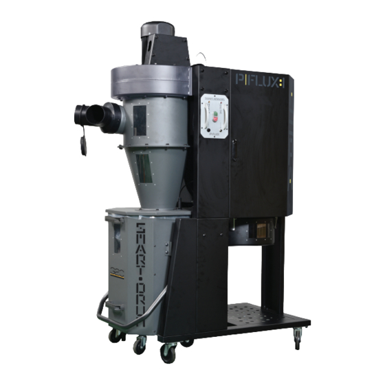
- Page 1 1.5HP CYCLONE 1 MICRON CANISTER | HEPA CANISTER...
- Page 2 TABLE OF CONTENTS Important Safety Instructions Safety Guidelines - Definitions General Safety Rules Additional Safety For Dust Collectors Power Connections Motor Specifications Grounding Instructions Functional Description Product Specifications Unpacking Assembly General Tool Assembly Maintenance Procedures Cleaning the Filter Changing the Filter Bag Emptying the Drum Routine Inspection Trouble Shooting...
-
Page 3: Important Safety Instructions
IMPORTANT SAFETY INSTRUCTIONS READ AND UNDERSTAND ALL WARNINGS AND OPERATING INSTRUCTIONS BEFORE USING THIS EQUIPMENT. Failure to follow all instructions listed below, may result in electric shock, fire, and/or serious personal injury or property damage. Woodworking can be dangerous if safe and proper operating procedures are not followed. As with all machinery, there are certain hazards involved with the operation of the product. - Page 4 4. Do not use this machine for other than its intended use. If used for other purposes, LAGUNA TOOLS INC., disclaims any real or implied warranty and holds itself harmless from any injury that may result from that use.
- Page 5 Your risk of exposure varies, depending on how often you do this type of work. To reduce your exposure to these chemicals, work in a well-ventilated area and work with approved safety equipment, such as face or dust masks that are specifically designed to filter out microscopic particles.
-
Page 6: Safety Guidelines - Definitions
22.Maintain a balanced stance at all times so that you do not fall or lean against the dust collector. Do not overreach or use excessive force to perform any machine operation. 23.Use the right tool at the correct speed and feed rate. Do not force a tool or attachment to do a job for which it was not designed. -
Page 7: General Safety Rules
Used without the safety alert symbol indicates potentially hazardous situation which, if not avoided, may result in property damage. GENERAL SAFETY RULES WARNING FAILURE TO FOLLOW THESE RULES MAY RESULT IN SERIOUS PERSONAL INJURY. FOR YOUR OWN SAFETY, READ AND UNDERSTAND THE INSTRUCTION MANUAL BEFORE OPERATING THE MACHINE. - Page 8 Dust allergies. Dust from certain woods may cause an allergic reaction in people and animals. Make sure you know what type of wood dust you will be exposed to in case there is a possibility of an allergic reaction. Wear respirator. Fine dust that is too small to be caught in the filter will be blown into the ambient air during operation.
-
Page 9: Power Connections
Regular cleaning. Regularly check/empty the collection bags or drum to avoid the buildup of fine dust that can increase the risk of fire. Make sure to regularly clean the surrounding area where the machine is operated—excessive dust buildup on overhead lights, heaters, electrical panels, or other heat sources will increase the risk of fire. -
Page 10: Motor Specifications
MOTOR SPECIFICATIONS Your machine is wired for 240volts, 50 HZ alternating current. Before connecting the machine to the power source, make sure the switch is in the "OFF" position. GROUNDING INSTRUCTIONS THIS MACHINE MUST BE GROUNDED WHILE IN USE TO PROTECT THE OPERATOR FROM ELECTRIC SHOCK. - Page 11 IN ALL CASES, MAKE CERTAIN THE RECEPTACLE IN QUESTION IS PROPERLY GROUNDED. IF YOU ARE NOT SURE, HAVE A QUALIFIED ELECTRICIAN CHECK THE RECEPTACLE. 240 VOLT Single-Phase Operation The motor supplied with your machine is a single voltage, 240 volt motor. It is shipped ready-to-run for 240 volt operation.
- Page 12 PROGRAMMING THE REMOTE CONTROL 1. Ensure the machine is switch ON before programming the remote control. 2. Press the Black Receiver set button on the bottom of the remote switch until you hear two beeps. 3. Press the Remote set button on your hand held controller simultaneously with the RED button until you hear three beeps to complete the set up.
-
Page 13: Product Specifications
PRODUCT SPECIFICATIONS Motor 1100w (1.5hp) Power Supply 220-240V / 50Hz / 1PH Running Amp (with 6" inlet) 9A @ 240v Recommended Breaker Size (MCB) 20 Amps (Type D) Airflow (Traditional Method) 1786m3/hour (1051cfm) Airflow (Realistic Method) 1224m3/hour (720cfm) Max. Static Pressure 256mm in water (10.1") Fan Diameter 340mm (13.5") - Page 14 Declaration of Conformity for CE Marking Charnwood Machinery Ltd Cedar Court Walker Road Bardon Hill Leicestershire LE67 1TU England Declare that Industrial Dust Collector & Air Cleaner Models B Flux, C Flux1, C Flux3, P Flux1, P Flux3 Conforms with the following Directives: Machinery Directive 2006/42/EC And further conforms with the following EU harmonized standard;...
- Page 15 UNPACKING Your 1.5HP Mobile Dust Cyclone comes packed in a single box. Before attempting to assemble this machine, follow these directions for unpacking: 1. Carefully cut the banding straps and remove them from the box. 2. Cut along the tape line at the top of the box. 3.
-
Page 16: General Tool Assembly
GENERAL TOOL ASSEMBLY This step requires two adults. This 1.5 HP Mobile Dust Cyclone is heavy, be careful when lifting and handling it! Failure to comply may cause serious injury and/or damage to the machine and/or property! Tools Required 10mm wrench / 12mm wrench / 14mm wrench Phillips screwdriver 4mm hex wrench / 5mm hex wrench To assemble your dust cyclone, follow these steps:... - Page 17 Step Two: Remove the base which has been fastened to the (3) top upright supports. Step Three: Secure the (4) 4” wheels to the underside of the base using (16) 5/16”*3/4” hex bolts and (16) 5/16”*od18*2T flat washers. 1.5HP Mobile Dust Cyclone Manual...
- Page 18 Step Four: Turn the base around with it standing on the (4) 4” wheels and secure the three lower upright support panels using (6) 3/8”*3/4” hex bolts and (6) 3/8”*OD23*2t flat washers. Each lower upright support panels numbered for its specific location. A –...
- Page 19 Step Six: Secure the base with (3) lower upright support panels to the unit using (6) 5/16”*3/4” hex bolts and (6) 5/16”*OD18*2t flat washers. Step Seven: Secure the (3) upright support reinforcement plates using (12) 5/16”*3/4” hex bolts and (12) 5/16”*OD18*2t flat washers. 1.5HP Mobile Dust Cyclone Manual...
- Page 20 Step Eight: With the help of another person, lift the unit up carefully to the right side up with the motor on top and the wheels at the bottom. Step Nine: Attach the canister filter back in place and secure with clamp. It does not matter which side you choose to position the clamp.
- Page 21 Step Ten: Attach the canister filter end cap to the canister filter using the (4) latches. Cover the 4” hook up with the 4” rubber plug. Step Eleven: Secure the lower triangular support plate to the base using 5/16”*3/4” hex bolts and (2) 5/16”*OD18*2t flat washers.
- Page 22 Step Twelve: Locate the two foot pedal bars provided. There is a left side and right side. To identify the correct side, look for the protruding nut, circled in red below. It should be facing upwards when you place the bars on the floor. LEFT RIGHT Step Thirteen: Ensure that the foot pedal bar is the correct side and slide the...
- Page 23 Step Fourteen: Secure the foot pedal support to the lower upright support panel using (4) 5/16”*1/2” carriage bolts, (4) 5/16”*OD18*2t flat washers and (4) 5/16” hex nuts. Then secure the foot pedal bar to this support using (4) 5/16”*1-3/4” hex bolts, (8)5/16”*OD18*2t flat washers and (4) 5/16” hex nuts. Follow the same steps for the opposite side.
- Page 24 Step Sixteen: Attach the cover plate over the foot pedal assembly. Secure using (6) 1/4”*3/4” hex bolts and (6) 1/4”*OD19*2t flat washers. Follow the same steps for the opposite side. Step Seventeen: Attach the two ends of the Octagon foot pedal to the nut on the foot pedal bar 1.5HP Mobile Dust Cyclone Manual...
- Page 25 Step Eighteen: Secure the topping to the nut on the foot peddle bar. Follow this step on the opposite side. Step Nineteen: Secure the topping with (2) M8*30mm hex bolts. 1.5HP Mobile Dust Cyclone Manual...
- Page 26 Step Twenty: Align the bolt hole on the movable supporting brace on the foot peddle bar with the bolt hole on the octagon foot peddle. Step Twenty One: Secure the movable supporting brace on the foot peddle bar with the octagon foot peddle using (2) 3/8”*21mm hex bolts.
- Page 27 Step Twenty Two: Apply foam tape to the cone flange before attaching the drum lid. Secure the Octagon drum lid to the cyclone funnel using (6) 5/16”*3/4” hex bolts, (12) 5/16”*OD18*2t flat washers and (6) 5/16” hex nuts. Make sure to first attach all the bolts on before tightening the bolts.
- Page 28 Step Twenty Four: To adjust the distance of the sensor to detect the dust waste level use the white plastic pin that was provided in the hardware box. Step Twenty Five: Using the white plastic pin, insert the sharp point into the top end of the proximity sensor that is on top of the drum lid.
- Page 29 Step Twenty Six: Assemble the Octagon drum. Locate the drum base panel, which is stamped, it does not matter which side faces inside, and secure the (4) 3” wheels using (8) 3/8”*OD23*2t flat washers and (4) 3/8” hex nuts.. Use the flat wrench provided to fasten tightly.
- Page 30 Step Twenty Eight: The panels have labels R and L on them to show you which panels should be bolted together to prevent any confusion. Please assemble them together per photo below. Step Twenty Nine: Both the left and right side lift panels have three bolt holes on them.
- Page 31 Step Thirty: Take the Octagon base panel with wheels and secure on to the bottom of the drum using M4*12mm sheet metal thread bolts Step Thirty One: Take the plastic bolt end caps to cover all the bolt ends on the inside of the Octagon drum using (40) plastic end caps.
- Page 32 Step Thirty Two: Once completing the assembly, apply silicone to the inside of the drum including the base to seal and prevent air leakages. Silicone Step Thirty Three: Attach the handles to the top and bottom end on the front panel with the window display using (4) flat head Philip bolt, (4) 5/16”*OD23*2t flat washers and (4) 5/16”...
- Page 33 Step Thirty Four: Attach the rubber gasket to the top inner edges of the Octagon drum. The wider end of the gasket goes up. You will need tin snips to trim any excess rubber gasket after completing the seal. Rubber gasket Step Thirty Five: Place the vacuum suction ring inside before inserting the plastic bag in the Octagon drum.
- Page 34 Step Thirty Six: Insert the plastic bag inside the Octagon drum. Open and spread out the plastic bag to the corners and edges Step Thirty Seven: Lift the foot peddle bar. Align the Octagon drum window to the center point of the drum lid and push the drum in. Lower the foot peddle bar to seal the drum tight for normal machine operation.
- Page 35 Step Thirty Eight: Make sure when aligning the drum that both the left and right side lift plates are over the topping on the foot peddle bar assembly before lifting the foot peddle bar up. When not aligned, the drum will not be fully sealed and will interfere with the air flow.
- Page 36 Step Forty: Apply foam tape to the hole on the dust chute before securing the pressure switch using (4) M4*12MM sheet metal thread bolts. Step Forty One: Locate the Ø1-1/4”*230mm black flex hose and two Ø1-1/4” hose clamps in the hardware box. Connect the one end of the flex hose to the vacuum suction tube which is located on the top end of the cyclone cone.
- Page 37 Step Forty Two: If you do not want to use a plastic bag inside the octagon collection drum, you need to block off the negative pressure. There is a little pack containing the items needed to do this. You will also need take the (4) 1/4”*1/2”...
- Page 38 Step Forty Four: Take the one of the cover plates, (2) 1/4”*1/2” carriage bolts, (2) 1/4”*OD19*2t flat washers and (2) 1/4” hex nuts and secure the cover plate to the opening on the top of the drum. For the bottom holes do the same, but first use foam tape to cover the square opening before bolting on the cover plate.
- Page 39 Step Forty Six: All the assembly steps have been completed. 1.5HP Mobile Dust Cyclone Manual...
-
Page 40: Maintenance Procedures
MAINTENANCE PROCEDURES CLEANING THE FILTER To ensure proper operation of this Mobile Dust Cyclone, the HEPA canister filter must have adequate air flow. This means the filter must be regularly maintained by carefully blowing the filter clean using compressed air and an air gun to release built-up particulates trapped between the filter pleats. -
Page 41: Emptying The Drum
EMPTYING THE CANISTER END CAP Periodically check the canister end cap, if it is more than one third full, it is recommended that you empty it. NOTE: If the canister end cap gets too full, the dust particulates may be recirculated back into the canister filter obstructing air flow and exposing the user to potentially harmful particulates. -
Page 42: Troubleshooting Guide
TROUBLESHOOTING GUIDE Symptom Possible Cause Possible Solution Machine Power supply switched Ensure power supply is ON and does not OFF or is faulty. has the correct voltage. start or a breaker Wall fuse/circuit breaker is Ensure adequate circuit size; trips. blown/tripped. - Page 43 Loud, Machine is on uneven Stabilize on a flat surface. repetitive surface. noise, or excessive Damaged/Unbalanced Inspect impeller for dents, vibration impeller. bends, loose fins. Replace if coming from needed. cyclone Loose connections. Check and re-tighten all fasteners. Replace the motor and Impeller is loose.
- Page 44 Parts Breakdown 山富機械公司 2016.08.25 出圖章 1.5HP Mobile Dust Cyclone Manual...
- Page 45 SECTION A (Close up view) 山富 出 1.5HP Mobile Dust Cyclone Manual...
- Page 46 SECTION B (Close up view) 1.5HP Mobile Dust Cyclone Manual...
- Page 47 SECTION C (Close up view) 1.5HP Mobile Dust Cyclone Manual...
- Page 48 SECTION D (Close up view) 1.5HP Mobile Dust Cyclone Manual...
- Page 49 Part List Ref No Part Name Description Q’TY MOTOR 1.5HP/240V/50Hz/1Phase MOTOR GASKET MOTOR SUPPORT BASE HEX LOCK BOLT 5/16”*5/8” FLAT WASHER 3/8”*OD23*2t HEX BOLT 3/8”*1” HEX NUT 3/8” FLAT WASHER 5/16”*OD18*2t HEX BOLT 5/16”*3/4” SWITCH PLATE HEX BOLT 1/4”*3/4” FLAT WASHER 1/4”*OD19*1t LOCK WASHER 3/8”...
- Page 50 Ref No Part Name Description Q’TY 5/16”*3/4” HEX BOLT FLAT WASHER 5/16”*OD18*2t LOWER UPRIGHT SUPPORT TWO DOT TOP UPRIGHT SUPPORT THREE DOT LOWER UPRIGHT SUPPORT THREE DOT HEX BOLT 5/16”*3/4” FLAT WASHER 5/16”*OD18*2t HEX BOLT 5/16”*3/4” FLAT WASHER 5/16”*OD18*2t HEX NUT 5/16”...
- Page 51 Ref No Part Name Description Q’TY OCTAGON DRUM FOOT PEDDLE 520*226*350 Ø24*30 TOPPING HEX BOLT M8*30mm HEX BOLT 3/8”*21mm HEX LOCK NUT 3/8” HEX BOLT 3/8”*1-1/2” HEX LOCK NUT 3/8” TRIANGULAR SUPPORT PLATE 170*102*28 HEX BOLT 5/16”*1-3/4” FLAT WASHER 5/16”*OD18*2t HEX NUT 5/16”...
- Page 52 Ref No Part Name Description Q’TY HANDLE FLAT WASHER 5/16”*OD23*2t HEX NUT 5/16” DRUM CASTER 3”*3/8” FLAT WASHER 3/8”*OD23*2t HEX NUT 3/8” OCTAGON DRUM BACK PANEL OCTAGON DRUM RIGHT PANEL OCTAGON DRUM LEFT PANEL LEFT SIDE PLATE RIGHT SIDE PLATE CARRIAGE BOLT 1/4”*1/2”...
- Page 53 Ref No Part Name Description Q’TY HEX BOLT 5/16”*3/4” FLAT WASHER 5/16”*OD18*2t HEX NUT 5/16” WINDOW OCTAGON DRUM LID HEX BOLT 5/16”*3/4” FLAT WASHER 5/16”*OD18*2t HEX NUT 5/16” PLUG MSP-16 AGL-16 RUBBER GASKET 140CM Ø400 BAND CLAMP Ø400 SPRING BAND CLAMP Ø400*611L CANISTER FILTER CANISTER END CAP...
- Page 54 Ref No Part Name Description Q’TY DOOR HANDLE HINGE CL-209 HEX BOLT M5*10mm COVER PLATE RIGHT COVER PLATE LEFT HEX BOLT 1/4”*3/4” FLAT WASHER 1/4”*OD19*1t CANISTER FILTER SHIELD HEX BOLT 1/4”*3/4” FLAT WASHER 1/4”*OD19*1t RIVET FLAT WASHER 1*8”*OD8*1t RIVET NUT 1/4”...
- Page 55 Ref No Part Name Description Q’TY FLAT WASHER 1/4”*OD19*2t HEX NUT 1/4” VACUUM SUCTION RING CONTROL BOX CONTROL PANEL ANODIZED CONTROL PANEL SUPPORT PLATE ROUND HEAD BOLT M4*10mm PHILIP HD BOLT M4*6mm RUBBER PLUG 30*60mm HOSE CLAMP 1-1/4” CONTROL PANEL HANDLE PHILIP HD BOLT M4*6mm 1.5HP Mobile Dust Cyclone Manual...
- Page 56 For After Sales & Service: Charnwood Machinery Ltd Walker Road, Hilltop Industrial Estate, Bardon, Leicestershire, LE67 1TU, United Kingdom Tel. +44 (0) 1530 516 926 sales@lagunatools.uk www.lagunatools.uk 1.5HP Mobile Dust Cyclone Manual...
Need help?
Do you have a question about the P Flux 1 and is the answer not in the manual?
Questions and answers