Table of Contents
Advertisement
Advertisement
Table of Contents

Subscribe to Our Youtube Channel
Related Manuals for laguna X Flux 10


Summary of Contents for laguna X Flux 10
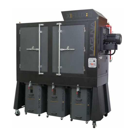
- Page 1 10HP EXPLOSION-PROOF CONTAINED SYSTEM...
- Page 2 TABLE OF CONTENTS Important Safety Instructions Safety Guidelines - Definitions General Safety Rules Additional Safety For Dust Collectors Power Connections Motor Specifications Grounding Instructions Key Features and Components Functional Description Product Specifications Unpacking Assembly General Tool Assembly Maintenance Procedures Cleaning the Filter Changing the Filter Bag Emptying the Drum...
-
Page 3: Important Safety Instructions
IMPORTANT SAFETY INSTRUCTIONS READ AND UNDERSTAND ALL WARNINGS AND OPERATING INSTRUCTIONS BEFORE USING THIS EQUIPMENT. Failure to follow all instructions listed below, may result in electric shock, fire, and/or serious personal injury or property damage. Woodworking can be dangerous if safe and proper operating procedures are not followed. As with all machinery, there are certain hazards involved with the operation of the product. - Page 4 4. Do not use this machine for other than its intended use. If used for other purposes, LAGUNA TOOLS INC., disclaims any real or implied warranty and holds itself harmless from any injury that may result from that use.
- Page 5 Crystalline silica from bricks, cement and other masonry products. Arsenic and chromium from chemically treated lumber. Your risk of exposure varies, depending on how often you do this type of work. To reduce your exposure to these chemicals, work in a well-ventilated area and work with approved safety equipment, such as face or dust masks that are specifically designed to filter out microscopic particles.
-
Page 6: Safety Guidelines - Definitions
21.Give your work undivided attention. Looking around, carrying on a conversation and “horse-play” are careless acts that can result in serious injury. 22.Maintain a balanced stance at all times so that you do not fall or lean against the dust collector. -
Page 7: General Safety Rules
Indicates a potentially hazardous situation which, if not avoided, may result in minor or moderate injury. Used without the safety alert symbol indicates potentially hazardous situation which, if not avoided, may result in property damage. GENERAL SAFETY RULES WARNING FAILURE TO FOLLOW THESE RULES MAY RESULT IN SERIOUS PERSONAL INJURY. - Page 8 Hazardous dust. Dust created while using machinery may cause cancer, birth defects, or long-term respiratory damage. Be aware of dust hazards associated with each work piece material, and always wear a NIOSH-approved respirator to reduce your risk. Dust allergies. Dust from certain woods may cause an allergic reaction in people and animals.
-
Page 9: Refer To Them Often And Use Them To Instruct Others
Static electricity. Plastic dust lines generate high amounts of static electricity as dust chips pass through them. Although rare, sparks caused by static electricity can cause explosions or fire. To reduce this risk, make sure all dust lines are thoroughly grounded by using a grounding wire. -
Page 10: Power Connections
POWER CONNECTIONS DO NOT EXPOSE THE MACHINE TO RAIN OR OPERATE THE MACHINE IN DAMP LOCATIONS. 10HP Explosion‐proof Vacuum Dust Collector Manual ... -
Page 11: Motor Specifications
MOTOR SPECIFICATIONS Your machine is wired for 220 volts, 60 HZ alternating current. Before connecting the machine to the power source, make sure the switch is in the "OFF" position. GROUNDING INSTRUCTIONS THIS MACHINE MUST BE GROUNDED WHILE IN USE TO PROTECT THE OPERATOR FROM ELECTRIC SHOCK. - Page 12 220 VOLT Three-Phase Operation The motor supplied with your machine is a 220 volt motor. It is shipped ready-to-run for 220 volt operation. FUNCTION High frequency remote control switch Canister Filter detection Octagon drum detection On board circuit breaker ...
-
Page 13: Product Specifications
PRODUCT SPECIFICATIONS Motor Specs: 10 HP Electrical Specs: 220V / 60Hz / 3PH / 3450 RPM Running AMP (with 12” inlet) 28A at 220V Air Volume: 4700CFM (cubic feet per minute) Max. static pressure 11 Inches of water Fan size 15.5”... - Page 14 UNPACKING Your 10HP Explosion-proof Vacuum Dust Collector comes packed in a single wooden crate. Before attempting to assemble this machine, follow these directions for unpacking: 1. Carefully remove the wooden crate walls. 2. Carefully take out the machine components from the box and set aside. 3.
-
Page 15: General Tool Assembly
GENERAL TOOL ASSEMBLY This step requires two adults. This 10HP Explosion- proof Vacuum Dust Collector is heavy, be careful when lifting and handling it! Failure to comply may cause serious injury and/or damage to the machine and/or property! Tools Required 10mm wrench / 12mm wrench / 14mm wrench Phillips screwdriver 4mm hex wrench / 5mm hex wrench... - Page 16 Step Two: Secure the four wheels to the upright support panels using (16) 3/8”*1” hex bolts and (16) 3/8”*OD23*2t flat washers. Step Three. Secure the upright support to the right side of the machine when facing the control panel.
- Page 17 Step Three. Secure the upright support to the left side of the machine when facing the control panel. Use (13) 3/8”*1” hex bolts and (13) 3/8”*OD23*2t flat washers. Step Four: Secure the latch base plate to the front side of the drum lid using (2) 3/16”*3/8”...
- Page 18 Step Five: Secure the casters to the drum base panel using (8) 3/8”*OD23*2T flat washers and (4) 3/8” nuts. Step Six: Assemble the front and back panel to the drum base using (10) 5/16”*5/8” Philip hd bolts, (20) 5/16”*OD18*2t flat washers and (10) 5/16” nuts. 10HP Explosion‐proof Vacuum Dust Collector Manual ...
- Page 19 Step Seven: Assemble the side panels to the drum using (6) 5/16”*5/8” Philip hd bolts, (12) 5/16”*OD18*2t flat washers and (6) 5/16” nuts to secure the base. And then use (16) 5/16”*5/8” Philip hd bolts, (16) 5/16”*OD18*2t flat washers and (16) 5/16”...
- Page 20 Step Nine: Assemble the latch to the drum using (4) 3/16”*3/8” round head thread bolts. Step Ten: Attach the 2-1/2”*2M flex hose to the drum and drum lid. Do the same for the other two drums. 10HP Explosion‐proof Vacuum Dust Collector Manual ...
- Page 21 Step Eleven: Place the vacuum suction ring inside before inserting the plastic bag in the Octagon drum. Vacuum suction ring Step Twelve: Once completing the assembly, apply silicone to the inside of the drum including the base to seal and prevent air leakages. Silicone 10HP Explosion‐proof Vacuum Dust Collector Manual ...
- Page 22 Step Thirteen: Attach the 12” intake to the left side of the machine as shown below using (10) 5/16”*3/4” hex bolts and (10) 5/16”*OD18*2t flat washers. Step Fourteen: All the assembly steps have been completed.. 10HP Explosion‐proof Vacuum Dust Collector Manual ...
-
Page 23: Cleaning The Filter
CLEANING THE FILTER To ensure proper operation of this Dust Cyclone, the canister filter must have adequate air flow. This means the filter must be regularly maintained by carefully blowing the filter clean using compressed air and an air gun to release built-up particulates trapped between the filter pleats. - Page 24 Loosen the bolt off of the rotation shaft as shown below. Set the shaft aside for later use. Keep the bolt for use when reassembling the rotation shaft. 3. Remove the adjustable clamp from the canister filter located at the bottom to remove the canister filter from the housing.
-
Page 25: Emptying The Drum
4. With the canister filter removed use a compressed air gun to thoroughly clean between the pleats, both inside and outside. RE-ASSEMBLING THE CANISTER FILTER AFTER CLEANING 1. With the aid of another person, carefully re-insert the canister filter repeating steps above in reverse. -
Page 26: Routine Inspection
2. Roll it away from the machine, inspect and empty as needed. ROUTINE INSPECTION It is a good idea to routinely inspect any quality woodworking tool in order to keep it in optimum condition. This includes inspecting all hardware for tightness, ensuring the filter is clean, and cleaning debris and grime from any surfaces and moving parts. -
Page 27: Troubleshooting Guide
TROUBLESHOOTING GUIDE Symptom Possible Cause Possible Solution Machine Power supply switched Ensure power supply is ON and does not OFF or is faulty. has the correct voltage. start or a breaker Wall fuse/circuit breaker is Ensure adequate circuit size; trips. - Page 28 Loud, Machine is on uneven Stabilize on a flat surface. repetitive surface. noise, or excessive Damaged/Unbalanced Inspect impeller for dents, vibration impeller. bends, loose fins. Replace if coming from needed. cyclone Loose connections. Check and re-tighten all fasteners. Replace the motor and Impeller is loose.
-
Page 29: Parts Breakdown
Parts Breakdown 山富機械公司 2016.05.19 出圖章 10HP Explosion‐proof Vacuum Dust Collector Manual ... -
Page 30: Part List
Part List Ref No Part Name Description Q’TY UPRIGHT SUPPORT STAND 2 26 HEX BOLT 3/8”*1” 26 FLAT WASHER 3/8”*OD23*2t 4 MACHINE CASTER 16 HEX BOLT 3/8”*1” 16 FLAT WASHER 3/8”*OD23*2t 1 UPPER BODY 1 LOWER BODY HEX BOLT 3/8”*1”... -
Page 31: Hex Lock Nut
Ref No Part Name Description Q’TY 3 HEX LOCK NUT 1/4” 3 WINDOW 30 RIVET 1 MACHINE BODY – SIDE PANEL 18 HEX BOLT 3/8”*1” FLAT WASHER 3/8”*OD23*2t 30 HEX LOCK NUT 3/8” 12 1 MACHINE BODY – MIDDLE PANEL 23 ... - Page 32 Ref No Part Name Description Q’TY 2 RIGHT SUPPORT BASE 18-1 2 18-2 LEFT SUPPORT BASE 8 THREAD BOLT 5/16”*3/4” 1 19-1 RIGHT DOOR 1 19-2 LEFT DOOR DOOR HANDLE 2 HINGE BASE – LOWER 4 4 HINGE BASE – TOP 8 ...
-
Page 33: Flat Washer
Ref No Part Name Description Q’TY 55 FLAT WASHER 3/8”*OD23*2t 23 HEX LOCK NUT 3/8” 4 RING 3/8”*1” 1 SILENCER 4 HEX BOLT 5/16”*3/4” FLAT WASHER 5/16”*OD18*2t 4 DUST CHUTE 1 10 HEX BOLT 3/8”*1” 10 FLAT WASHER 3/8”*OD23*2t 1 ... - Page 34 Ref No Part Name Description Q’TY 12 FLAT WASHER 3/8”*OD23*2t 1 GASKET 4 HEX BOLT 5/8”*2” 4 FLAT WASHER 5/8”*OD40*2.5t 4 HEX NUT 5/8” LOCK WASHER 5/8” 4 MOTOR 10HP/220V/3PHASE/60HZ 1 4 HEX BOLT 1/2”*1-1/2” 8 FLAT WASHER 1/2”*OD34*2.5t 4 ...
- Page 35 Ref No Part Name Description Q’TY 3 OCTAGON DRUM BACK PANEL 3 DRUM VACUUM TUBE 12 PHILIP HD BOLT 1/4”*5/8” 12 FLAT WASHER 1/4”*OD18*2t 6 HOSE CONNECTOR HOSE CLAMP 2-1/2” 6 GRAY FLEX HOSE 2-1/2”*2M 3 6 OCTAGON DRUM SIDE PANEL 60 ...
- Page 36 Laguna Tools is not responsible for errors or omissions. Specifications subject to change. Machines may be shown with optional accessories. © 2018, Laguna Tools, Inc. LAGUNA® and the LAGUNA Logo® are the registered trademarks of Laguna Tools, Inc. All rights reserved.
Need help?
Do you have a question about the X Flux 10 and is the answer not in the manual?
Questions and answers