Table of Contents
Advertisement
OPERATING AND PARTS MANUAL
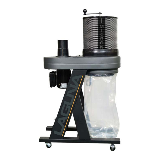
1HP One stage Dust Collector
Model:
BFLUX1
Please read and save these instructions. Read carefully before attempting to
assemble, install, operate or maintain the product described. Protect
yourself and others by observing all safety information. Failure to comply
with instructions could result in personal injury and/or property damage!
Retain instructions for future reference.
Advertisement
Table of Contents

Subscribe to Our Youtube Channel
Related Manuals for laguna BFLUX1


Summary of Contents for laguna BFLUX1
- Page 1 OPERATING AND PARTS MANUAL 1HP One stage Dust Collector Model: BFLUX1 Please read and save these instructions. Read carefully before attempting to assemble, install, operate or maintain the product described. Protect yourself and others by observing all safety information. Failure to comply with instructions could result in personal injury and/or property damage! Retain instructions for future reference.
-
Page 2: Table Of Contents
TABLE OF CONTENTS Important Safety Instructions Safety Guidelines - Definitions General Safety Rules Additional Safety For Dust Collectors Power Connections Motor Specifications Grounding Instructions Key Features and Components Functional Description Product Specifications Assembly General Tool Assembly Maintenance Procedures Cleaning the Filter Routine Inspection Trouble Shooting Parts breakdown and parts list... -
Page 3: Important Safety Instructions
IMPORTANT SAFETY INSTRUCTIONS READ AND UNDERSTAND ALL WARNINGS AND OPERATING INSTRUCTIONS BEFORE USING THIS EQUIPMENT. Failure to follow all instructions listed below, may result in electric shock, fire, and/or serious personal injury or property damage. Woodworking can be dangerous if safe and proper operating procedures are not followed. - Page 4 4. Do not use this machine for other than its intended use. If used for other purposes, LAGUNA TOOLS INC., disclaims any real or implied warranty and holds itself harmless from any injury that may result from that use.
- Page 5 8. Some dust created by power sanding, sawing, grinding, drilling and other construction activities contain chemicals known to cause cancer, birth defects or other reproductive harm. Some examples of these chemicals are: • Lead from lead based paint. • Crystalline silica from bricks, cement and other masonry products.
-
Page 6: Safety Guidelines - Definitions
18.Keep the floor around the machine clean and free of scrap material, oil and grease. 19.Keep visitors a safe distance from the work area. Keep children away. 20.Make your workshop child proof with padlocks, master switches or by removing starter keys. 21.Give your work undivided attention. -
Page 7: General Safety Rules
Indicates an imminently hazardous situation which, if not avoided, will result in death or serious injury. Indicates a potentially hazardous situation which, if not avoided, could result in death or serious injury. Indicates a potentially hazardous situation which, if not avoided, may result in minor or moderate injury. -
Page 8: Additional Safety For Dust Collectors
FAILURE TO FOLLOW THESE RULES MAY RESULT IN SERIOUS INJURY. ADDITIONAL SAFETY FOR DUST COLLECTORS Intended use. This dust collector is only intended for collecting wood dust and chips from woodworking machines. Do not use this dust collector to collect metal, dirt, pebbles, drywall, asbestos, lead paint, silica, liquids, aerosols, or any flammable, combustible, or hazardous materials. - Page 9 cause serious personal injury or damage to the machine. Always keep small animals and children away from open dust collection inlets. Avoiding sparks. Do not allow steel or rocks to strike the impeller—this may produce sparks. Sparks can smolder in wood dust for a long time before a fire is detected. If you accidentally cut Into wood containing tramp metal (nails, staples, spikes, etc.), immediately turn off the dust collector, disconnect it from power, and wait for the...
-
Page 10: Power Connections
POWER CONNECTIONS A separate electrical circuit should be used for your machines. This circuit should not be less than #12 wire and should be protected with a 15 Amp time lag fuse. If an extension cord is used, use only 3-wire extension cords which have 3-prong grounding type plugs and matching receptacle which will accept the machine’s plug. - Page 11 Check with a qualified electrician or service personnel if the grounding instructions are not completely understood, or if in doubt as to whether the machine is properly grounded. Use only 3-wire extension cords that have 3-prong grounding type plugs and matching 3-conductor receptacles that accept the machine’s plug, as shown in Fig.
- Page 12 doubt, use the next heavier gauge. The smaller the gauge number, the heavier the cord. MINIMUM GAUGE EXTENSION CORD MINIMUM GAUGE EXTENSION CORD RECOMMENDED SIZES FOR USE WITH RECOMMENDED SIZES FOR USE WITH STATIONARY ELECTRIC MACHINES STATIONARY ELECTRIC MACHINES Ampere Total Length of Gauge of Ampere...
-
Page 13: Product Specifications
PRODUCT SPECIFICATIONS Motor 750w (1HP) Power Supply 220-240V / 50Hz / 1PH Running Amp (with 4" inlet) 4.7A @ 240v Recommended Breaker Size (MCB) Airflow (Traditional Method) 884m3/hour (520cfm) Airflow (Realistic Method) 748m3/hour (440cfm) Max. Static Pressure 123mm in water (4.86") Fan Diameter 230mm (9") Inlet Diameter... - Page 14 Declaration of Conformity for CE Marking Charnwood Machinery Ltd Cedar Court Walker Road Bardon Hill Leicestershire LE67 1TU England Declare that Industrial Dust Collector & Air Cleaner Models B Flux, C Flux1, C Flux3, P Flux1, P Flux3 Conforms with the following Directives: Machinery Directive 2006/42/EC And further conforms with the following EU harmonized standard;...
-
Page 15: General Tool Assembly
GENERAL TOOL ASSEMBLY Tools Required 12mm wrench by 14mm wrench (supplied in hardware pack) Phillips screwdriver (not supplied) SEVERE LACERATION HAZARD. TURN THE UNIT “OFF”, DISCONNECT THE UNIT from the power source and wait 2- 1/2 minutes to allow time for internal rotating components to stop before installing or removing accessories, before adjusting or changing set-ups, clearing clogs or when making repairs. - Page 16 3. Make sure you have the base in the position as shown below, with the four bolt holes facing up. 4. For each wheel, insert bolt from caster through the holes in the base of the dust collector (three are not shown). Tighten the caster to the base by turning the movable plate (A) in Fig.
- Page 17 SIDE SUPPORTS 1. Place the base with the casters on the bottom. Make sure you place the side with the two bolt holes on each leg of the base to your right side when looking down on it. See below on positioning; this is important for assembling the correct side support to the corresponding side.
- Page 18 3. The base below shows where each side support needs to go. Short R Long R Short L Long L 4. Place the Long side support labeled “L” in an upright position with the slant facing inwards towards the middle of the base. The angle of the picture below has been taken on the opposite side to show the label “L”.
- Page 19 5. Align the two holes in the bottom end of the long side support with the two holes in the base. Place a 5/16” flat washer onto the 5/16”x3/4” hex bolt and insert through each hole in the long side support and base.
- Page 20 7. Align the two holes on the top end of the short side support to with the two bolt holes on the middle of the long side support. Place a 5/16” flat washer onto the 5/16”x3/4” hex bolt and insert through each hole in the long side support and short side support.
- Page 21 Locate the support brace and place inside the two side supports. NOTE: MAKE SURE THE SUPPORT IS ATTACHED TO THE SIDE SUPPORTS CLOSEST TO THE MOTOR. Align the four holes in the support brace with the four holes in the side supports as shown below. Place a 5/16”...
- Page 22 ATTACHING THE MOTOR AND DUST CHUTE TO THE FRAME 1. Place the motor and dust chute on their side. 2. Align the four holes, two shown at C, on the top of the side supports (A) Fig. 3, with the four holes on the dust chute (B). 3.
- Page 23 INTAKE ADAPTER TO THE DUST CHUTE 1. Line up four holes in the intake adapter (one shown as X) Fig.4 with four holes in the dust chute. 2. Use the included #8 x 1/2” countersunk screws, fasten the intake adapter to the dust chute. SEVERE LACERATION HAZARD.
- Page 24 CANISTER FILTER TO CHUTE 1. Take the canister filter and fit the open end to the top channel on the dust chute. 2. Locate the adjustable band clamp from the hardware and take the end with the clamp and key bolt. Adjust the length of the band clamp by tightening or loosening the key bolt.
- Page 25 COLLECTION BAGS TO CHUTE DISCONNECT THE MACHINE FROM THE POWER SOURCE! USING THE CLOTH SNAP BAND RING: 1. Place the cloth-covered snap band ring (A) Fig. 5 inside the opening of the clear plastic collection bag. Fold about 6 inches of the bag around the snap band ring.
-
Page 26: Cleaning The Filter
CLEANING THE FILTER To ensure proper operation of this Dust Cyclone, the canister filter must have adequate air flow. This means the filter must be regularly maintained by carefully blowing the filter clean using compressed air and an air gun to release built-up particulates trapped between the filter pleats. -
Page 27: Trouble Shooting
TROUBLESHOOTING GUIDE Symptom Possible Cause Possible Solution Machine Power supply switched Ensure power supply is ON and does not OFF or is faulty. has the correct voltage. start or a breaker Wall fuse/circuit breaker is Ensure adequate circuit size; trips. blown/tripped. - Page 28 Motor fan hitting fan Check fan and cover; replace as cover. needed. Dust Canister end bag is full. Empty canister end bag. collector does not Filter is dirty. Clean filter. adequately collect dust Restricted duct line. Clean inlet adapter. or chips; poor Suction route is too long Move machine closer to the point...
- Page 29 Parts Breakdown 1HP One stage Dust Collector Manual...
- Page 30 Part List Ref No Part Name Description Q’TY DUST CHUTE INTAKE SPLITTER 4” HEX BOLT 5/16”*3/4” 5/16” SHEET METAL THREAD BOLT #8x1/2” HEX BOLT 5/16”*3/4” FLAT WASHER 5/16”*OD18*2t MOTOR BASE SUPPORT GASKET HEX SPRING BOLT 5/16”*5/8” HEX BOLT 5/16”*3/4” FLAT WASHER 5/16”*OD30*3t 9”...
- Page 31 Ref No Part Name Description Q’TY FLAT WASHER 1/4”*OD19*2t Ø70* Ø20.5*7t BEARING Ø350*300mm CANISTER FILTER ROTATION SHAFT SUPPPORT PLATE HEX BOLT 1/4”*5/8” FLAT WASHER 1/4”*OD13*1t CANVAS PEDAL LOCK NUT 1/4” FLAT WASHER 5/16”*OD23*2t HEX BOLT 5/16”*3/4” LOCK NUT 1/4” FLAT WASHER 1/4”*OD13*1t HEX BOLT 1/4”*3/4”...
- Page 32 For After Sales & Service: Charnwood Machinery Ltd Walker Road, Hilltop Industrial Estate, Bardon, Leicestershire, LE67 1TU, United Kingdom Tel. +44 (0) 1530 516 926 sales@lagunatools.uk www.lagunatools.uk 1HP One stage Dust Collector Manual...
Need help?
Do you have a question about the BFLUX1 and is the answer not in the manual?
Questions and answers