Table of Contents
Advertisement
Advertisement
Table of Contents

Subscribe to Our Youtube Channel
Related Manuals for laguna MDCCF32201


Summary of Contents for laguna MDCCF32201
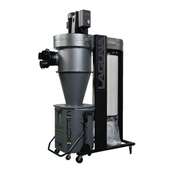
- Page 1 3HP CYCLONE 1 MICRON CANISTER...
- Page 2 TABLE OF CONTENTS Important Safety Instructions Safety Guidelines - Definitions General Safety Rules Additional Safety For Dust Collectors Power Connections Motor Specifications Grounding Instructions Key Features and Components Functional Description Product Specifications Unpacking Assembly General Tool Assembly Maintenance Procedures Cleaning the Filter Changing the Filter Bag Emptying the Drum Routine Inspection...
- Page 3 IMPORTANT SAFETY INSTRUCTIONS READ AND UNDERSTAND ALL WARNINGS AND OPERATING INSTRUCTIONS BEFORE USING THIS EQUIPMENT. Failure to follow all instructions listed below, may result in electric shock, fire, and/or serious personal injury or property damage. Woodworking can be dangerous if safe and proper operating procedures are not followed. As with all machinery, there are certain hazards involved with the operation of the product.
- Page 4 4. Do not use this machine for other than its intended use. If used for other purposes, LAGUNA TOOLS INC., disclaims any real or implied warranty and holds itself harmless from any injury that may result from that use.
- Page 5 Your risk of exposure varies, depending on how often you do this type of work. To reduce your exposure to these chemicals, work in a well-ventilated area and work with approved safety equipment, such as face or dust masks that are specifically designed to filter out microscopic particles.
- Page 6 22.Maintain a balanced stance at all times so that you do not fall or lean against the dust collector. Do not overreach or use excessive force to perform any machine operation. 23.Use the right tool at the correct speed and feed rate. Do not force a tool or attachment to do a job for which it was not designed.
-
Page 7: General Safety Rules
Used without the safety alert symbol indicates potentially hazardous situation which, if not avoided, may result in property damage. GENERAL SAFETY RULES WARNING FAILURE TO FOLLOW THESE RULES MAY RESULT IN SERIOUS PERSONAL INJURY. FOR YOUR OWN SAFETY, READ AND UNDERSTAND THE INSTRUCTION MANUAL BEFORE OPERATING THE MACHINE. - Page 8 Dust allergies. Dust from certain woods may cause an allergic reaction in people and animals. Make sure you know what type of wood dust you will be exposed to in case there is a possibility of an allergic reaction. Wear respirator. Fine dust that is too small to be caught in the filter will be blown into the ambient air during operation.
- Page 9 Regular cleaning. Regularly check/empty the collection bags or drum to avoid the buildup of fine dust that can increase the risk of fire. Make sure to regularly clean the surrounding area where the machine is operated—excessive dust buildup on overhead lights, heaters, electrical panels, or other heat sources will increase the risk of fire.
-
Page 10: Grounding Instructions
MOTOR SPECIFICATIONS Your machine is wired for 220 volts, 60 HZ alternating current. Before connecting the machine to the power source, make sure the switch is in the "OFF" position. GROUNDING INSTRUCTIONS THIS MACHINE MUST BE GROUNDED WHILE IN USE TO PROTECT THE OPERATOR FROM ELECTRIC SHOCK. - Page 11 IN ALL CASES, MAKE CERTAIN THE RECEPTACLE IN QUESTION IS PROPERLY GROUNDED. IF YOU ARE NOT SURE, HAVE A QUALIFIED ELECTRICIAN CHECK THE RECEPTACLE. 220 VOLT Single-Phase Operation The motor supplied with your machine is a 220 volt motor. It is shipped ready-to-run for 220 volt operation.
- Page 12 PROGRAMMING THE REMOTE CONTROL 1. Ensure the machine is switch ON before programming the remote control. 2. Press the BLACK set button on the bottom of the remote switch until you hear two beeps. 3. Press the Remote set button on your hand held controller simultaneously with the BLACK button until you hear three beeps to complete the set up.
- Page 13 PRODUCT SPECIFICATIONS Motor Specs: 3 HP Electrical Specs: 220V / 60Hz / 1PH / 3450 RPM Running AMP (with 8” inlet) 22A at 220V Air Volume: 1624CFM (cubic feet per minute) Max. static pressure 11.2 Inches of water Fan size 15.5”...
- Page 14 UNPACKING Your 3HP Mobile Dust Cyclone comes packed in a single box. Before attempting to assemble this machine, follow these directions for unpacking: 1. Carefully cut the banding straps and remove them from the box. 2. Cut along the tape line at the top of the box. 3.
- Page 15 GENERAL TOOL ASSEMBLY This step requires two adults. This 3HP Mobile Dust Cyclone is heavy, be careful when lifting and handling it! Failure to comply may cause serious injury and/or damage to the machine and/or property! Tools Required 10mm wrench / 12mm wrench / 14mm wrench Phillips screwdriver 4mm hex wrench / 5mm hex wrench To assemble your dust cyclone, follow these steps:...
- Page 16 Step Two: Secure the (4) 3” wheels to the underside of the base (G) using (16) 5/16”*3/4” hex bolts and (16) 5/16”*od18*2T flat washers. Step Three: Turn the base (G) around with it standing on the (4) 3” red wheels and secure the three lower upright support panels (R). using (6) 3/8”*3/4”...
- Page 17 Step Four: Install the foam tape to the upper and lower rims of the three components listed, Cyclone funnel, Cyclone barrel, and Intake cylinder. Step Five: Attach the intake cylinder to the dust chute using (4) 5/16”*5/8” hex spring bolts. Then, attach the cyclone barrel onto the dust chute using (12) 5/16”*3/4”...
- Page 18 Step Six: Secure the base with (3) lower upright support panels to the unit using (6) 5/16”*3/4” hex bolts and (6) 5/16”*OD18*2t flat washers. Step Seven: Secure the (3) upright support reinforcement plates (T) using (12) 5/16”*3/4” hex bolts and (12) 5/16”*OD18*2t flat washers. 3HP Mobile Dust Cyclone Manual...
- Page 19 Step Eight: With the help of another person, lift the unit up carefully to the right side up with the motor on top and the wheels at the bottom. Step Nine: Secure the lower triangular support plate to the base using 5/16”*3/4”...
- Page 20 Step Ten: Slide the Foot pedal bar into the opening on the lower upright support panel (R). Make sure the end of the bar is on the inside of the triangular support plate. Follow the same steps for the opposite side. Step Eleven: Secure the foot pedal support to the lower upright support panel using (4) 5/16”*1/2”...
- Page 21 Step Twelve: Secure the base of the foot pedal bar to the triangular support plate by holding the lower support plate vertically up against the foot pedal bar using (4)5/16”*1-3/4” hex bolts, (8) 5/16”*OD18*2t flat washers and (4) 5/16” hex nuts from the inside out.
- Page 22 Step Fourteen: Secure the topping to the nut on the foot pedal bar. Follow this step on the opposite side. Step Fifteen: Secure the topping with (2) M8*30mm hex bolts 3HP Mobile Dust Cyclone Manual...
- Page 23 Step Sixteen: Align the bolt hole on the movable supporting brace on the foot peddle bar with the bolt hole on the octagon foot peddle. Step Seventeen: Secure the movable supporting brace on the foot pedal bar with the octagon foot pedal using(2) 3/8”*46mm hex bolts.
- Page 24 Step Eighteen: Secure the Octagon drum lid to the cyclone funnel using (8) 5/16”*3/4” hex bolts, (16) 5/16”*OD18*2t flat washers and (8) 5/16” hex nuts.. Make sure to first attach all the bolts on before tightening the bolts. Failure to do will result in the drum lid not being able to align with the drum.
- Page 25 Step Twenty: Take the Octagon drum side panels and assemble together, secure with (40) M4*12mm sheet metal thread bolts. Take note of the left and right panels; do not assemble the incorrect sides. Refer to the next step.. Step Twenty One: The panels have labels R and L on them to show you which panels should be bolted together to prevent any confusion.
- Page 26 Step Twenty Two: Both the left and right side lift panels have three bolt holes on them. Take the matching side plate and secure to the outside of the panel. (Photo shown is the inside of the panel) using (6) 1/4”*1/2” carriage bolts, (6) 1/4”*OD19*2t flat washers and (6) 1/4”...
- Page 27 Step Twenty Four: Take the plastic bolt end caps to cover all the bolt ends on the inside of the Octagon drum using (40) plastic end caps. This step is necessary to prevent any injuries caused by the sharp end of the bolts. Step Twenty Five: Once completing the assembly, apply silicone to the inside of the drum including the base to seal and prevent air leakages and air flow loss.
- Page 28 Step Twenty Six: Attach the handles to the top and bottom end on the front panel with the window display using (4) flat head Philip bolt, (4) 5/16”*OD23*2t flat washers and (4) 5/16” hex nuts. Step Twenty Seven: Attach the rubber gasket to the top inner edges of the Octagon drum.
- Page 29 Step Twenty Eight: Insert the plastic bag inside the Octagon drum. Open and spread out the plastic bag to the corners and edges Step Twenty Nine: Place the drum insert inside over the plastic bag in the Octagon drum. Drum insert 3HP Mobile Dust Cyclone Manual...
- Page 30 Step Thirty: Lift the foot peddle bar. Align the Octagon drum window to the center point of the drum lid and push the drum in. Lower the foot peddle bar (s) to seal the drum tight for normal machine operation. Step Thirty One: Make sure when aligning the drum that both the left and right side lift plates are over the topping on the foot peddle bar assembly before lifting...
- Page 31 Step Thirty Two: Install the Remote Switch Box to the switch plate on the motor using (4) 1/4”*3/4” hex bolts and (4) 1/4”*OD19*2t flat washers. Step Thirty Three: Take the paddle and paddle branch and assemble together using (4) 1/4”*5/8” hex bolts, (8) 1/4”*OD13*1t flat washers and (4) 1/4” hex nuts. Step Thirty Four: Assemble the two paddle and paddle branch assemblies to the rotation shaft using (4) 1/4”*5/8”...
- Page 32 Step Thirty Five: Insert the rotation shaft assembly into the canister filter. Slightly bend the paddles to get them into the canister filter. Step Thirty Six: Assemble the canister filter to the dust chute. Tighten the band clamp and adjust the tightness accordingly to ensure the canister filter is tightly fitted onto the dust chute.
- Page 33 Step Thirty Seven: Attach the canister cover plate to the dust chute using (12) 3/16”*1/2” sheet metal thread bolts. Step Thirty Eight: From the bottom of the canister filter, push the rotation shaft through the hole in the middle of the canister cover plate. 3HP Mobile Dust Cyclone Manual...
- Page 34 Step Thirty Nine: While holding the rotation shaft above the hole, insert the bearing onto the rotation shaft and pushing it down to the canister cover plate. This will fix the rotation shaft in place and you will not need to keep holding it up. Secure the bearing using (4) 1/4”*3/4”...
- Page 35 Step Forty One: Attach and secure the rotation crank to the top of the rotation shaft using (1) 5/16”*3/4” hex bolt and (1) 5/16”*OD30*3t flat washer. Step Forty Two: All the assembly steps have been completed. 3HP Mobile Dust Cyclone Manual...
- Page 36 MAINTENANCE PROCEDURES CLEANING THE FILTER To ensure proper operation of this Mobile Dust Cyclone, the HEPA canister filter must have adequate air flow. This means the filter must be regularly maintained by carefully blowing the filter clean using compressed air and an air gun to release built-up particulates trapped between the filter pleats.
- Page 37 EMPTYING OR REPLACING THE FILTER BAG Periodically check the filter bag, if it is more than one third full, it is recommended that you empty it. NOTE: If the filter bag gets too full, the weight may force it to pull away from the band clamp, exposing the user to potentially harmful particulates.
-
Page 38: Troubleshooting Guide
TROUBLESHOOTING GUIDE Symptom Possible Cause Possible Solution Machine Power supply switched Ensure power supply is ON and does not OFF or is faulty. has the correct voltage. start or a breaker Wall fuse/circuit breaker is Ensure adequate circuit size; trips. blown/tripped. - Page 39 Loud, Machine is on uneven Stabilize on a flat surface. repetitive surface. noise, or excessive Damaged/Unbalanced Inspect impeller for dents, vibration impeller. bends, loose fins. Replace if coming from needed. cyclone Loose connections. Check and re-tighten all fasteners. Replace the motor and Impeller is loose.
-
Page 40: Parts Breakdown
Parts Breakdown 山富機械公司 2016.08.25 出圖章 MDC CF22201 SPARE PARTS LIST REV. C... - Page 41 SECTION A 山富機械 (Close up view) 2016. 出圖 MDC CF22201 SPARE PARTS LIST REV. C...
- Page 42 SECTION B (Close up view) MDC CF22201 SPARE PARTS LIST REV. C...
- Page 43 SECTION C (Close up view) MDC CF22201 SPARE PARTS LIST REV. C...
- Page 44 SECTION D (Close up view) MDC CF22201 SPARE PARTS LIST REV. C...
-
Page 45: Part List
Part List Ref No Part Name Description Q’TY MOTOR 3HP/220V/60Hz/1Phase MOTOR GASKET MOTOR SUPPORT BASE HEX LOCK BOLT 5/16”*5/8” FLAT WASHER 3/8”*OD23*2t HEX BOLT 3/8”*1” HEX NUT 3/8” FLAT WASHER 3/8”*OD23*2t HEX BOLT 3/8”*1-1/4” SWITCH PLATE HEX BOLT 1/4”*3/4” FLAT WASHER 1/4”*OD19*1t LOCK WASHER 3/8”... - Page 46 Ref No Part Name Description Q’TY FLAT WASHER 5/16”*OD18*2t LOWER UPRIGHT SUPPORT TWO DOT TOP UPRIGHT SUPPORT TWO DOT LOWER UPRIGHT SUPPORT TWO DOT HEX BOLT 5/16”*3/4” FLAT WASHER 5/16”*OD18*2t HEX BOLT 5/16”*1-3/4” FLAT WASHER 5/16”*OD18*2t HEX NUT 5/16” TOP UPRIGHT SUPPORT ONE DOT LOWER UPRIGHT SUPPORT ONE DOT...
- Page 47 Ref No Part Name Description Q’TY OCTAGON DRUM FOOT PEDDLE 520*226*350 TOPPING Ø24*30 HEX BOLT M8*30mm HEX BOLT 3/8”*21mm HEX LOCK NUT 3/8” HEX BOLT 3/8”*1-1/2” HEX LOCK NUT 3/8” TRIANGULAR SUPPORT PLATE 170*102*28 HEX BOLT 5/16”*1-3/4” FLAT WASHER 5/16”*OD18*2t HEX NUT 5/16”...
- Page 48 Ref No Part Name Description Q’TY FLAT HEAD PHILIP BOLT 5/16”*3/4” HANDLE FLAT WASHER 5/16”*OD23*2t HEX NUT 5/16” DRUM CASTER 3”*3/8” FLAT WASHER 3/8”*OD23*2t HEX NUT 3/8” OCTAGON DRUM BACK PANEL OCTAGON DRUM RIGHT PANEL OCTAGON DRUM LEFT PANEL LEFT SIDE PLATE RIGHT SIDE PLATE CARRIAGE BOLT 1/4”*1/2”...
- Page 49 Ref No Part Name Description Q’TY FLAT WASHER 5/16”*OD18*2t HEX BOLT 5/16”*3/4” FLAT WASHER 5/16”*OD18*2t HEX NUT 5/16” OCTAGON DRUM LID HEX BOLT 5/16”*3/4” FLAT WASHER 5/16”*OD18*2t HEX NUT 5/16” PLUG MSP-16 AGL-16 RUBBER GASKET 160CM BAND CLAMP Ø400 SPRING BAND CLAMP Ø400 ROTATION CRANK HEX BOLT...
- Page 50 Ref No Part Name Description Q’TY PADDLE BRANCH HEX LOCK NUT 1/4” ROTATION SHAFT CONNECTION HEX BOLT 5/16”*1-1/2” FLAT WASHER 5/16”*OD18*2t HEX LOCK NUT 5/16” CANISTER FILTER Ø400*900L ROTATION SHAFT BASE SHEET METAL PHILIP BOLT 3/16”*3/4” HEX BOLT 5/16”*3/4” FLAT WASHER 5/16”*OD23*2t FOAM TAPE 3*25mm*1.5M...
- Page 51 NOTES MDC CF32201 SPARE PARTS LIST REV. B...
- Page 52 Laguna Tools is not responsible for errors or omissions. Specifications subject to change. Machines may be shown with optional accessories. © 2017, Laguna Tools, Inc. LAGUNA® and the LAGUNA Logo® are the registered trademarks of Laguna Tools, Inc. All rights reserved.
Need help?
Do you have a question about the MDCCF32201 and is the answer not in the manual?
Questions and answers