Oriental motor BMU Series Operating Manual
Brushless motor
Hide thumbs
Also See for BMU Series:
- Operating manual (44 pages) ,
- Quick start manual (2 pages) ,
- Quick start manual (2 pages)
Table of Contents
Advertisement
HM-5186-6
Brushless Motor
BMU Series
200 W / 300 W / 400 W
OPERATING MANUAL
Thank you for purchasing an Oriental Motor product.
This Operating Manual describes product handling procedures and safety precautions.
• Please read it thoroughly to ensure safe operation.
• Always keep the manual where it is readily available.
Advertisement
Table of Contents

Related Manuals for Oriental motor BMU Series


Summary of Contents for Oriental motor BMU Series
- Page 1 BMU Series 200 W / 300 W / 400 W OPERATING MANUAL Thank you for purchasing an Oriental Motor product. This Operating Manual describes product handling procedures and safety precautions. • Please read it thoroughly to ensure safe operation. • Always keep the manual where it is readily available.
-
Page 2: Table Of Contents
Table of contents 1 Introduction ............3 10 Troubleshooting and remedial actions ...38 2 Safety precautions ..........4 11 Maintenance and inspection ......39 11.1 Inspection ............... 39 3 Precautions for use ........... 6 11.2 Warranty ..............39 4 Preparation ............7 11.3 Disposal .............. -
Page 3: Introduction
The product described in this manual is designed and manufactured to be incorporated in general industrial equipment. Do not use for any other purpose. Oriental Motor Co., Ltd. is not responsible for any compensation for damage caused through failure to observe this warning. -
Page 4: Safety Precautions
• Do not disassemble or modify the driver. Doing so may result in electric shock, injury or damage to equipment. Should you require inspection or repair of internal parts, please contact the Oriental Motor branch or sales office from which you purchased the product. - Page 5 Safety precautions CAUTION • Do not use the driver beyond the specifications. Doing so may result in fire, electric shock, injury or damage to equipment. • Do not insert an object into the openings in the driver. Doing so may result in fire, electric shock, injury or damage to equipment.
-
Page 6: Precautions For Use
Precautions for use 3 Precautions for use This chapter covers restrictions and requirements the user should consider when using the product. Be sure to match the motor output power with the driver output power. z Connect protective devices to the power line Connect a circuit breaker or earth leakage breaker to the driver’s power line to protect the primary circuit. -
Page 7: Preparation
□ Instructions and Precautions for Safe Use .... copy 4.2 How to identify the product model BMUD 200 - C ① Driver type BMUD: BMU series driver ② Output power 200: 200 W 300: 300 W 400: 400 W ①... -
Page 8: Names And Functions Of Parts
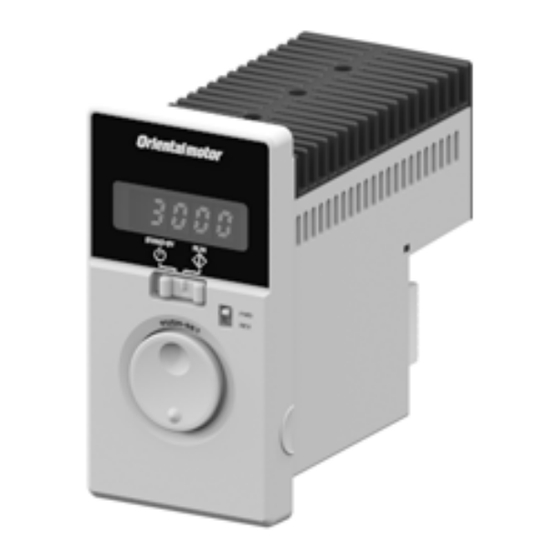
Preparation 4.5 Names and functions of parts Front side Rear side When the front panel is attached Protective lm Use after removing Display the protective lm. Operation switch Rotation direction Motor connector switch Sensor connector (CN2) (CN3) Main power supply Setting dial connector (CN1) I/O signals connector... -
Page 9: Installation
Installation 5 Installation This chapter explains the installation location and installation methods of the driver. 5.1 Installation location Install the driver in a well-ventilated place where they can be inspected easily and the following conditions are satisfied: • Inside an enclosure that is installed indoors (provide vent holes) •... - Page 10 Installation „ Installation method Install the driver to a flat metal plate offering excellent vibration resistance. Remove the front panel of the driver and secure the two mounting holes using screws and nuts (M4 or No.8-32UNC: not supplied). Tighten the screws until no gaps remain between the driver and mounting plate. •...
-
Page 11: Connection
Connection 6 Connection 6.1 Connecting the motor and driver There are the connector type motor and the cable type motor. „ Connector type Connect the motor and driver using the connection cable (sold separately). The connection cables are provided up to 10 m (32.8 ft.). - Page 12 Connection „ Cable type Motor cable Grounding [ 0.5 m (1.6 ft.) ] Protective Earth Terminal Be sure to ground. To power supply ⇒ p.14 Protective Earth Terminal Grounding Be sure to ground. Connect the motor connector (white) of the motor cable to the CN2, and the sensor connector (black) to the CN3 on the driver.
-
Page 13: Grounding
Connection 6.2 Grounding Be sure to ground the motor and driver. Failure to do so may result in electric shock or damage to the product. Note Static electricity may cause damage to the product if the Protective Earth Terminals are not grounded. „... -
Page 14: Connecting The Power Supply
Connection 6.3 Connecting the power supply Connect the power cable to the CN1 on the driver. Check the specification of the power supply voltage for the driver before applying a voltage. Note If a voltage exceeding the rated range is applied, the driver may be damaged. Input power supply Connecting method Single-phase 100-120 V... -
Page 15: Connecting The I/O Signals
Connection 6.4 Connecting the I/O signals Connect the I/O signals to CN4 on the driver. Refer to p.18 for connection examples with a programmable controller. Connecting the lead wire • Applicable lead wire: AWG24 to 18 (0.2 to 0.75 mm •... -
Page 16: Connection Diagram
Connection „ Using a external control equipment with a built-in clamp diode If a external control equipment with a built-in clamp diode is used, External control Driver equipment a leakage path may form and cause the motor to operate even when the external control equipment power is off, as long as the +5 V driver power is on. - Page 17 Connection z When using the external power supply This is a connection example for when the external power supply is used for input signals. The I/O signal in the brackets [ ] is the assignment at the time of shipment. Driver Main circuit Motor connection...
- Page 18 Connection „ Connection example for I/O signals and programmable controller This is a connection example when the motor is operated using a transistor output type programmable controller. Sink logic Programmable controller Driver 24 VDC IN-COM0 820 : 6.6 k: 820 : 6.6 k: 820 : 6.6 k:...
-
Page 19: Operating
Operating 7 Operating 7.1 Operation overview Operating by front panel Operating by programmable controller The motor can be operated and stopped The motor can be operated and stopped using with the operation switch on the front panel. external signals. Driver Programmable Driver Motor... - Page 20 Operating „ Inputting the power Display is lit Indication: Rotation speed When inputting the power, if the operation switch is set to the RUN side, the alarm code Note " " (prevention of operation at power-on) is displayed, and the operation cannot be executed.
-
Page 21: Operating By Programmable Controller
Operating 7.3 Operating by programmable controller The motor can be operated and stopped externally. AC power supply Programmable Connection: p.14 Motor Driver controller When the motor is operated and stopped externally, the "external operation signal input" parameter ( is required to change. „... - Page 22 Operating z When the setting is "ON" Operation by switches on the front panel: Enable When turning the operation input signal ON while the operation switch is set to the RUN side, the motor rotates. When the operation switch is set to the "STAND-BY" side, the motor decelerates to a stop even if the operation input signal is being ON.
- Page 23 Operating „ Operating with multiple speeds Data of up to 4 speeds can be operated with switching the data by the external signal. Explanation of graphic symbols Data setting method MODE key FUNCTION key Example: Set the rotation speed to 3000 r/min (change from 50 r/min) Power ON Setting dial Panel display...
- Page 24 Operating „ Switching the motor rotation direction When turning the FWD input or REV input ON, the motor rotation direction varies depending on the state of the rotation direction switch. The rotation direction shown in the figure below is as viewed from the motor output shaft. External operation input Rotation direction switch FWD input ON...
-
Page 25: Convenient Functions
Convenient functions 8 Convenient functions 8.1 Functions list The following functions are available for this product. Reference Functions Description page Displays the rotation speed of the motor output shaft. Rotation speed 30, 28 Displays by converting the motor rotation speed into the rotation speed of the gearhead output shaft. -
Page 26: Setting Items And Panel Displays
Convenient functions 8.2 Setting items and panel displays The display is lit The display blinks This is a state being set. The setting can be changed while the display blinks. After the setting was changed, it is determined when the display changes from blinking to lighting. - Page 27 Convenient functions Explanation of graphic symbols : Press the MODE key : Press the FUNCTION key When the front panel is removed : Turn the setting dial Setting dial : Press the setting dial Parameter mode Return to the "monitor mode" External Speed operation...
-
Page 28: Parameter List
Convenient functions 8.3 Parameter list Operation mode: Parameter mode Factory Item Display Description Setting range setting Sets the speed reduction ratio relative to the rotation speed of the motor output shaft. Displays the speed calculated based on the speed reduction ratio Speed reduction ratio 1.00 to 9999 1.00... - Page 29 Convenient functions Factory Item Display Description Setting range setting Not used ALARM-OUT1 OUT0 output function selection SPEED-OUT Assigns the output signals to the ALARM-OUT2 external output terminals. MOVE OUT1 output function selection Sets the time to output the alarm after detecting the overload condition when Overload alarm detection time a load up to the limited duty region...
-
Page 30: Items Displayed On The Driver
Convenient functions 8.4 Items displayed on the driver Operation mode: Monitor mode Item Display Description • Monitors the rotation speed of the motor. • Monitors the rotation speed of the gear output shaft or conveyor transfer speed when the Rotation speed * "speed reduction ratio"... -
Page 31: Setting The Operation Data
Convenient functions z Display the conveyor transfer speed To display the conveyor transfer speed, calculate the conveyor speed reduction ratio by using the formula below and set to the "speed reduction ratio" parameter. Gearhead gear ratio Conveyor speed reduction ratio = Feed rate per motor revolution Pulley diameter [m] ×... -
Page 32: Setting The Acceleration Time And Deceleration Time
Convenient functions 8.6 Setting the acceleration time and deceleration time The acceleration time and deceleration time can be set so that an impact is not applied to a load when the motor is started or stopped. There are the following two methods to set. The setting by the "acceleration/deceleration time potentiometer"... -
Page 33: Data Locking For The Set Data
Convenient functions 8.7 Data locking for the set data The data setting can be locked so that the set rotation speed does not change. The setting of data and parameters cannot be changed using the setting dial while locking. Remove the front panel and perform the operations shown in the next. -
Page 34: Holding A Load At Motor Standstill
Note power and wait for minimum 1 minute before doing so. If the product does not operate properly after the power is cycled, the internal circuit may be damaged. Contact your nearest Oriental Motor branch or sales office. • The motor stops instantaneously at the time of external stop ( ). - Page 35 Alarms and warnings „ Alarm list Alarm Alarm Alarm type Cause Remedial action code reset * 1 Excessive current has flown through the driver Check the wiring between the driver Overcurrent due to ground fault, etc. and motor for damage. possible •...
- Page 36 • If the motor does not operate properly after the power is cycled, internal circuit damage is suspected. Note Please contact your nearest Oriental Motor branch or sales office. • Continuing the operation without removing the cause of the problem may cause malfunction of the equipment.
-
Page 37: Warnings
Alarms and warnings 9.2 Warnings The warning types and records can be displayed on the monitor mode. When a warning generates, the WNG output will be turned ON. The WNG output is not assigned to the output terminal at the time of shipment. Refer to p.29 "Description of I/O signals." „... -
Page 38: Troubleshooting And Remedial Actions
Troubleshooting and remedial actions 10 Troubleshooting and remedial actions During motor operation, the motor or driver may fail to function properly due to an improper speed setting or wiring. When the motor cannot be operated correctly, refer to the contents provided in this section and take appropriate action. If the problem persists, contact your nearest office. -
Page 39: Maintenance And Inspection
It is recommended that periodic inspections for the items listed below are conducted after each operation of the motor. If an abnormal condition is noted, discontinue any use and contact your nearest Oriental Motor sales office. • Do not conduct the insulation resistance measurement or dielectric strength test with the motor and driver Note connected. -
Page 40: Cables And Peripheral Equipment (Sold Separately)
Cables and peripheral equipment(sold separately) 12 Cables and peripheral equipment (sold separately) „ Power supply cable This cable is used to connect the driver to the power supply. • For single-phase 100 VAC (with plug) * • For single-phase 100-120/200-240 VAC •... -
Page 41: Regulations And Standards
Regulations and standards 13 Regulations and standards 13.1 UL Standards, CSA Standards This product is recognized by UL under the UL and CSA Standards. 13.2 CE Marking/UKCA Marking This product is affixed with the marks under the following directives/regulations. „ EU Low Voltage Directive/UK Electrical Equipment (Safety) Regulation Installation conditions Ⅱ... - Page 42 Regulations and standards z The driver is not provided with the ground fault protection. Wire the product in accordance with “Wiring example having considered ground fault protection. ” Also observe the followings. • Earth leakage breaker: Rated sensitivity current 30 mA •...
-
Page 43: Eu Rohs Directive/Uk Rohs Regulation
Regulations and standards Three-phase 200-240 V • TN power distribution systems Earth leakage breaker Driver Fault loop Grounding • TT power distribution systems Earth leakage breaker Driver Grounding Grounding Fault loop „ EU EMC Directive/UK EMC Regulation Refer to"Conformity to the EMC" on p.44 for details about conformity. 13.3 EU RoHS Directive/UK RoHS Regulation This product does not contain the substances exceeding the restriction values. -
Page 44: Conformity To The Emc
The use of the following installation and wiring methods will enable the motor and driver to be compliant with the EMC. Oriental Motor conducts EMC testing on its motors and driver in accordance with "Example of motor and driver installation and wiring" on p.45. - Page 45 • Use a dedicated connection cable (sold separately) for the connection between the connector type motor and the driver. Use an accessory connection cable when extending the wiring distance between the motor and the driver. The EMC measures are conducted using the Oriental Motor connection cable. „ Example of motor and driver installation and wiring The figure shows the connector type.
-
Page 46: Specifications
Specifications 14 Specifications „ Specifications The value in a state where the gearhead is not combined is described in each specification for the "rated torque," "instantaneous peak torque," "rated rotation speed" and "speed control range." Refer to the operating manual of the motor for the motor model name. BLM5200HP BLM5300HP BLM5400HP... - Page 47 Specifications „ Dimension Mass: 0.8 kg (1.76 lb.) [Unit: mm (in.)] 61 ( 2.40 ) 116.6 ( 4.59 ) 15.5 ( 0.61 ) 68 (2.68) ( 1.18 ± 0.5 ± 0.02 3.2 ( 0.13 ) [ 0.5 ( 0.02 )] [ 0.5 ( 0.02 )] 2×Ø4.5 ( 0.177 ) Thru 12.5 ( 0.49 )
- Page 48 If a new copy is required to replace an original manual that has been damaged or lost, please contact your nearest Oriental Motor branch or sales office. • Oriental Motor shall not be liable whatsoever for any problems relating to industrial property rights arising from use of any information, circuit, equipment or device provided or referenced in this manual.
Need help?
Do you have a question about the BMU Series and is the answer not in the manual?
Questions and answers