Table of Contents
Advertisement
Available languages
Available languages
Quick Links
この説明書をお読みになり 、 正しくお使いください。
お読みになった後も 、 後日お役に立ちますので
・ MODEL FM-2023 だけでお使いいただくことはできません。必ず MODEL FM-202 ス
テーションへ接続してお使いください。
・ MODEL FM-202 ステーションの詳細については、MODEL FM-202 ステーションの
取扱説明書をご覧ください。
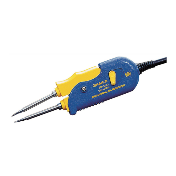
ミニパラレルリムーバー
取扱説明書
お買い上げいただきありがとうございます。
大切に保管しておいてください。
1. セット内容 ............................................................1
2. 仕様 ......................................................................1
3. 安全及び取扱い上のご注意 ..................................2
4. 各部名称 ...............................................................3
5. 組み立て ...............................................................3
6. 使用方法 ...............................................................4
7. メンテナンス ........................................................7
8. トラブル発生時に .................................................8
9. 部品リスト ..........................................................10
10. 配線図 ................................................................11
●
●
注 意
目次
Advertisement
Chapters
Table of Contents

Related Manuals for Hakko Electronics FM-2023


Summary of Contents for Hakko Electronics FM-2023
-
Page 1: Table Of Contents
取扱説明書 ● お買い上げいただきありがとうございます。 この説明書をお読みになり 、 正しくお使いください。 お読みになった後も 、 後日お役に立ちますので 大切に保管しておいてください。 ● 注 意 ・ MODEL FM-2023 だけでお使いいただくことはできません。必ず MODEL FM-202 ス テーションへ接続してお使いください。 ・ MODEL FM-202 ステーションの詳細については、MODEL FM‐202 ステーションの 取扱説明書をご覧ください。 目次 1. セット内容 ............1 2. 仕様 ..............1 3. 安全及び取扱い上のご注意 ........2 4. 各部名称 ...............3 5. -
Page 2: セット内容
こて先 (I型) MODEL FM-2023 ミニパラレルリムーバー コンポーネント皿 こて先IDダミーバー 耐熱パッド クリーニングスポンジ ● 適用モデル MODEL FM‐2023 は必ず MODEL FM‐202 ステーションへ接続してご使用ください。 2. 仕様 ● MODEL FM-2023 ミ ニパラ レルリ ムーバー 消費電力 140 W (24 V) 制御温度 200〜400゜ C こて先アース間抵抗 2 Ω以下 漏れ電圧 2 mV以下 接続コー ド... -
Page 3: 安全及び取扱い上のご注意
電源を入れると、こて先温度は 200 〜 400℃の高温に達します。 取扱いを誤ると、やけど・火災の恐れがありますので、以下の注意事項を必ず守っ てください。 ● こて先やこて先周辺の金属部分に触れない。 ● 燃えやすいものの近くで使用しない。 ● 周囲の人に「高温につき危険である」ことを知らせる。 ● 使用を中断・終了する時や、その場を離れる時は電源を切る。 ● 部品交換時や収納時は必ず電源を切り、十分に冷えたことを確認する。 注 意 故障を防ぎ、作業環境を安全に保つため、以下の注意事項を必ず守ってください。 ● この取扱説明書で特に説明されている以外の用途に使用しない。 ● こて先設定温度を 400℃より高くしない。 ● はんだかすを取るために、MODEL FM-2023 を作業台に打ちつけるなど強い衝 撃を与えない。 ● 本品を改造しない。 ● 交換部品には 、 純正部品を使用する。 ● 水につけたりぬれた手で使用しない。 ● 使用中に煙が発生するので、十分な換気を行う。 ● コードの抜き差しはプラグを持って行う。... -
Page 4: 各部名称
3. 接続 1. プラグを MODEL FM-202 のレセプタ プラ グか ら カチ ッ と音が クルに接続します。 する ま で完全に レセプタ クル 2. MODEL FM-2023 をこてホルダーに 差し込みます。 挿します。 3. 電源コードのプラグを電源に差し込みま す。必ずアースを取ってください。 プラ グ を それ以上進ま な く なる ま で押し 込み、 ロ ッ クピン を押さ ずにプラ グ を抜... -
Page 5: 使用方法
6. 使用方法 ● 操作と表示 MODEL FM-202 の取扱説明書を参照し てください。 注意: MODEL FM-202 MODEL FM-2023 こて先にはこて先 ID は ステーシ ョ ン 付いておりません。必ずこて先 ID ダミー バーを使用してください。 プロセスゲー ト 注記: レセプタ クル こて先 ID ダミーバーをプロセスゲートへ 挿入したとき、ブザーが 3 回鳴れば、こて 先 ID 読取りエラーが発生しています。こて 先 ID ダミーバーをもう一度挿入してくださ... - Page 6 ●使用手順 1. 温度を設定する 注意: 温度を決して400℃より高い温度に設定 しないでください。ステーションが破損す ることがあります。行う作業の種類によっ て温度を設定してください。 注記: 2 つのこて先がこて部へ挿入されれば、温 2. ハンドルのスイッチレバー 調が開始されます。 を切り替える セットになっている両方のこて先を必ず挿 入してください。片方だけを挿入しても、 レバー操作で次のふた通りの動きが選べ こて部は熱くなりません。 ます。 ・レバー表示マーク「R」が見える。すな 注意: わちこて先が閉じている状態の時から こて先が高温になりすぎると、プリント基 は、スリーブの後部を操作することで 板を傷付け、プリントされた配線パターン こて先の開閉ができます。 が切れてしまうことがあります。通常の作 ・レバー表示マーク「N」が見える。すな 業では、こて先温度を 300℃より低い温度 わちこて先が開いている状態の時から に設定するようお薦めします。可能な最も は、スリーブの前部を操作することで 低い効率的な温度にすれば、熱に弱い部品 こて先の開閉ができます。 を保護できるだけでなく、熱によるこて先 の劣化を防止するのにも役立ちます。 3. はんだまたはフラックスを 塗る...
- Page 7 ●カードと温度設定の変 更 MODEL FM-202 の取扱説明書を参照し てください。 ●こて先の交換 こて先の取外しと挿入 FM-2023 24V-140W こて先の取外し: ハンドルを握り、耐熱パッドを使ってこ て先を持ち、こて先をこて部から引き抜 この部分を持って、こて先を取り外します。 きます。 こて先の挿入: FM-2023 24V-140W こて先を挿入する前に、こて先 ID ダミー バーの ID 側を、ブザーが 1 回鳴るまでプ この部分を持ってハンドルへ挿入します。 ロセスゲートへ挿入してください。 注意: こて先の先端部分を持ち、こて先をこて こて先は高温になっています。やけどの原 部へ挿入します。こて先がそれ以上進ま 因となりますので、取扱いには十分ご注意 なくなるまで押します。 ください。耐熱パッドで熱いこて先を長時 間つかまないでください。...
-
Page 8: メンテナンス
ピン 1 〜ピン 3 間 - 7 〜 9 Ω ピン 5 〜ピン 3 間 - 8 〜 10K Ω ピン 7 〜ピン 4 間 - 7 〜 9 Ω ピン 8 〜ピン 4 間 - 8 〜 10K Ω 抵抗値が上記の値と異なる場合は、MODEL FM-2023 を交換してください。... -
Page 9: トラブル発生時に
8. トラブル発生時に 警告: 修理を実施する際、電源プラグは必ず抜いてください。 感電の恐れがあります。 ● こて先が熱くならない。 : こて先はしっかりと差し込まれていま 点検 すか。 センサーエラー が表示 ● 対処 : こて先を最後まで差し込んでください。 されている。 : 接続コードが断線していませんか。 ヒー 点検 ター/センサーは切れていませんか。 対処 : 本書の接続コードの断線およびヒー ター/センサー切れの調べ方の項を参 照してください。 : こて先の設定温度が高すぎませんか。 ● こて先にはんだがのら 点検 対処 : 適正温度に設定してください。 ない。 : こて先に酸化物が付着していませんか。 点検 対処... - Page 10 : 接続コードが断線していませんか。 ● はんだこてエラーを示 点検 対処 : 「接続コード断線の調べ方」の項を参照 す が表示される。 してください。 : MODEL FM-2023 の プ ラ グ が 外 れ て 点検 いませんか。 対処 : MODEL FM-2023 を接続してください。 ● 下限設定温度エラー : はんだ除去対象物に対してこて先が小 点検 さすぎませんか。 が頻発する。 対処 : 「接続コード断線の調べ方」の項を参照 してください。...
-
Page 11: 部品リスト
9. 部品リスト ●ミニパラレルリムーバー 図番 品番 品名 仕様 B2300 耐熱パッド B2847 こて先IDダミーバー B2848 こてホルダー ねじ付 A1519 クリーニングスポンジ B2849 コンポーネント皿 こて先なし ミニパラレールリムーバー FM2023-02 ●交換こて先 品番 品名 サイズ A 形状 ------------------ T9-I こて先/CHIP I ------------- T9-L1 こて先/CHIP 1L 1 mm T9-L2 こて先/CHIP 2L 2 mm... -
Page 12: 配線図
10. 配線図 基板/表示用 LED1 黄 青 茶 紫... - Page 13 高調溫式平行除錫鑷子 使用說明書 日本白光牌 ● 承蒙惠顧,謹致謝忱。 使用 MODEL FM-2023 前,請詳閱本 使用說明書,正確使用。 閱後請妥為收存,以備日後查閱。 ● 注 意 ● MODEL FM-2023 無法單獨使用。請務必接續 MODEL FM-202 控制臺 使用之。 ● 關於 MODEL FM-202 控制臺之詳細,請參閱 MODEL FM-202 控制臺 之使用說明書。 目 錄 1. 包裝清單 ..............13 2. 規格 ................13 3. 安全及使用上的注意事項 ........14 4. 各部名稱 ..............15 5. 組裝 ................15 6. 使用方法 ..............16 7. 保養 ................19 8. 排除故障指南 ............20 9. 部件清單 ..............22...
-
Page 14: 包裝清單
迷你平行除錫鑷子 ........1 焊鐵頭 ID 棒 ..........1 抗熱墊片 ............1 焊鐵支架 ............1 清潔海綿 ............1 零件小盤 ............1 焊鐵頭 (T9-I)2 支/一套 ......1 ● 適用機種 MODEL FM-2023 請務必接續 MODEL FM-202 控制臺使用。 2. 規格... -
Page 15: 安全及使用上的注意事項
本說明書之注意事項, 區分為如下之 「警告」 「注意」 二者而加以表示。請充分理解其內容之後, 再閱讀本文。 警 告: 濫用可能導致使用者死亡或負重傷。 注 意: 濫用可能導致使用者受傷或對涉及物體造成實質破壞。 注 記: 表示所說明工程之重要程序或事項。 注 意 當電源接通時,焊鐵頭溫度會達到攝氏 200 ∼ 400℃的高溫。 ● 切勿碰觸焊鐵頭或其周圍的金屬部分。 ● 切勿在易燃物附近使用本機器。 ● 通知周圍的人「高溫危險」 。 ● 使用暫停、結束或要離開時應關掉電源。 ● 更換部件或收起本機器之前,應關掉電源,並待機器冷卻至室溫。 注 意 為了防止故障並維護作業環境安全起見,請務必遵守以下之注意事項。 ● 本使用說明書所特別說明以外之用途,不加以使用。 ● 不使焊鐵頭設定溫度高於 400℃。 ● 不將 MODEL FM-2023 敲打作業台等試圖以強力衝擊去除焊錫屑。 ● 切勿改裝本產品。 ● 更換部件時,必僅使用 Hakko 正廠部件。 ● 切勿弄濕本產品或以濕手使用。 ● 使用中會產生煙霧,請充分做好通風。 ● 拔出電線時,請抓住插頭。切勿拉住電線。... -
Page 16: 各部名稱
或 634-02) 。 把支架部掛到焊鐵座下部的支部分,然後 用螺絲在支架上部鎖緊。 圖 2 如圖組裝: 1. 切勿讓焊鐵頭從焊鐵支架露出。 (參照 圖 1 ) 圖 1 2. 將螺絲鎖緊支架之前確認焊鐵支架應盡 掛在焊鐵座上部。 圖 3 (參照 圖 2 及 3 ) 3. 接續 1. 將插頭接續到 MODEL FM-202 之插座。 2. 將 MODEL FM-2023 置於焊鐵座上。 3. 將電源線之插頭插入電源座。請務必做 好接地。 注記: MODEL FM-2023 實施防靜電處理,所以 務必請接地之後再使用,以充分發揮功效。... -
Page 17: 使用方法
6. 使用方法 ●控制與顯示 請參照 MODEL FM-202 之使用說明書。 注意: MODEL FM-2023 焊 鐵 頭 沒 有 焊 鐵 頭 ID, 請使用焊鐵頭 ID 棒。 注記: 將焊鐵頭 ID 棒插入處理閘時,蜂鳴器響三 下的話,表示發生焊鐵頭 ID 棒讀取錯誤。 請再次重新插入焊鐵頭 ID 棒。焊鐵頭 ID 被剝掉,或破掉的話,處理閘即無法讀取 注意: ID。 請勿將異物、焊鐵頭的尖端,或是本商品 不能使用的焊鐵頭插入處理閘。恐會造成 破損。 注記:... - Page 18 6. 達到設定溫度時蜂鳴器會響,溫度顯示 部右下之發熱元件通電指示燈開始閃 亮。 ●使用程序 注記: 2 個焊鐵頭被插入焊鐵部的話, 溫調即開始。 1. 設定溫度 請務必插入成組的 2 個焊鐵頭。僅插入 1 個的話,焊鐵部不會變熱。 注意: 溫度請絕對不要設定為高於 400℃之溫度。 注意: 控制臺可能會破損。請依據要進行行作業 焊鐵頭溫度變為太高的話,會傷及印刷電 之種類設定溫度。 路板,可能使所印刷電路線圖樣斷掉。通 常之作業中,HAKKO 建議您將焊鐵頭溫 度設定為低於 300℃之溫度。設定成可能 之最低效率溫度的話,不僅可保護耐熱較 弱之部件,並有幫助於防止熱度造成焊鐵 頭惡化。 2. 塗抹焊錫或焊劑 印刷電路板上沒有充足之焊錫,或焊錫黏 著部份太小時,請在基板上塗抹焊錫或焊 劑。焊鐵頭上亦可塗抹焊錫。 焊錫 3. 溶解焊錫 部件 將焊鐵頭置於焊錫黏著部份,溶解焊錫。...
- Page 19 ●插卡與溫度設定之更換 請參照 MODEL FM-202 的使用說明書。 ●更換焊鐵頭 取下或插入焊鐵頭 取下焊鐵頭: 握住手柄,使用抗熱墊片拿著焊鐵頭,將 焊鐵頭自焊鐵部拔出。 插入焊鐵頭: 插入焊鐵頭之前,將焊鐵頭之焊鐵頭 ID 側 插入處理閘,直到蜂鳴器響一下為止。 拿著焊鐵頭之尖端部份,將焊鐵頭插入焊 鐵部。焊鐵頭一直推到無法再進入為止。 注意: 焊鐵頭會很燙。可能引起燙傷,使用時請 充分注意。 請勿以抗熱墊片拿焊鐵頭太久。...
- Page 20 1. 在兩邊的手柄上安裝正常的(發熱元件 阻抗正常的)焊鐵頭。 2. 測定插頭接腳之間的電阻值。 接腳 1 – 3 7 ∼ 9Ω 接腳 5– 3 8 ∼ 10KΩ 接腳 7– 4 7 ∼ 9Ω 接腳 8– 4 8 ∼ 10KΩ 如 果 電 阻 值 與 上 述 不 同 時, 請 更 換 MODEL FM-2023。...
-
Page 21: 排除故障指南
動作 : 請使用 Hakko 599B 焊鐵頭清潔器或 沾濕的清潔海棉來清潔焊鐵頭, 以去 除氧化物。 : 所輸入焊鐵頭 ID 棒號碼正確嗎 ? 檢查 動作 : 請正確輸入。 : 組裝電線壞了嗎 ? ●焊鐵錯誤 被顯示。 檢查 動作 : 請參閱“組裝電線破損檢查方法”項 目。 : MODE FM-2023 之插頭未插上嗎 ? 檢查 動作 : 請插上 MODEL FM-2023。... - Page 22 用方法” 。 注記: 將焊鐵頭 ID 棒插入處理閘時,蜂鳴器響三 下的話,表示發生焊鐵頭 ID 棒讀取錯誤。 請再次重新插入焊鐵頭 ID 棒。焊鐵頭 ID 被剝掉,或破掉的話,處理閘即無法讀取 ID。 ●表示發熱元件端子短路 : 焊鐵頭是 MODEL FM-2023 用的嗎 ? 檢查 動作 : 請關閉電源開關,正確插入 MODEL 錯誤之 被顯示。 FM-2023 焊鐵頭, 再重新打開電源開 關。 ●焊鐵頭無法關閉。 : 焊鐵頭彼此之間夾有異物嗎 ? 檢查...
-
Page 23: 部件清單
9. 部件清單 T9-I T9-L1 T9-L2... -
Page 24: 電路圖
10. 電路圖... - Page 25 MODEL FM-2023. Keep this manual readily accessible for reference. CAUTION • The MODEL FM-2023 cannot function by itself. It must be con- nected to an MODEL FM-202 soldering station. • Specific information can be found in the instruction manual for your MODEL FM-202 soldering station.
-
Page 26: Packing List
Component bed Heat resistant pad Tip ID number key Cleaning sponge l Applicable Models In order to function, the MODEL FM-2023 must be connected to the MODEL FM-202 soldering station. 2. SPECIFICATIONS MODEL FM-2023 Mini Parallel Remover Power Consumption 140W (24 V) Temperature Range 200 –... -
Page 27: Warnings, Cautions And Notes
Do not set the tip temperature higher than 400°C. l Do not rap the MODEL FM-2023 against the work bench to shake off residual solder, or otherwise subject the iron to severe shocks. l Do not modify the unit. -
Page 28: Part Names
When the plug ‘clicks’, 1. Connect the plug to the MODEL FM-202. it is fully inserted. Receptacle 2. Place the MODEL FM-2023 in the iron holder. 3. Plug the power cord into the power supply. Be sure to ground the unit. - Page 29 Please refer to the MODEL FM-202 in- struction manual. MODEL FM-202 CAUTION: Soldering station MODEL FM-2023 tips do not have a tip ID. Use the Tip ID number key. Process gate Receptacle NOTE: If the buzzer sounds three times when the...
- Page 30 Very high tip temperatures may damage the printed circuit board, possibly causing 2. Switch lever on the handle the printed pattern to become detached. The MODEL FM-2023 is HAKKO recommends setting the tip tem- perature below 300°C for all normal work. double acting.
- Page 31 Please refer to the MODEL FM-202 In- struction manual. l Replacing the tip Removing and inserting the tip: FM-2023 24V-140W Removing the tip: Hold the handle and pull the tip out of Hold the handpiece at the front to remove tip.
- Page 32 Checking the connection cord 1. Insert a set of verified tips in both sides of the for breakage handle. 2. Measure the resistance value between two pins. Pin 1 - Pin 3 7~9Ω Pin 5 - Pin 3 8~10KΩ Pin 7 - Pin 4 7~9Ω Pin 8 - Pin 4 8~10KΩ If the measured value exceeds above values, replace the MODEL FM-2023.
- Page 33 : Is the connection cord broken? l The soldering iron error ACTION : See “Checking the connection is displayed. cord for breakage”. • The LED heater lamp does not CHECK : Is the MODEL FM-2023 plug dis- light. connected? ACTION : Connect the MODEL FM-2023.
- Page 34 Tip ID number key. If the code bar is torn or damaged the process gate will not be able to read it. CHECK : Is the tip for MODEL FM-2023? l Heater terminal short ACTION : Turn the power switch OFF and in- circuit error...
- Page 35 9. PARTS LIST...
- Page 36 10. WIRING DIAGRAM P.W.B/LED LED1 http://www.hakko.com HEAD OFFICE 〒556-0024 大阪市浪速区塩草2丁目4番5号 4-5, Shiokusa 2-chome, Naniwa-ku, Osaka 556-0024 JAPAN T E L : (06) 6561-1574 (代) F AX : (06) 6568-0821 TEL:+81-6-6561-3225 FAX:+81-6-6561-8466 http://www.hakko.com E-mail:sales@hakko.com OVERSEAS AFFILIATES U.S.A.: AMERICAN HAKKO PRODUCTS, INC. TEL: (661) 294-0090 FAX: (661) 294-0096 Toll Free (800)88-HAKKO 4 2 5 5 6 http://www.hakkousa.com...
Need help?
Do you have a question about the FM-2023 and is the answer not in the manual?
Questions and answers