Table of Contents
Advertisement
Quick Links
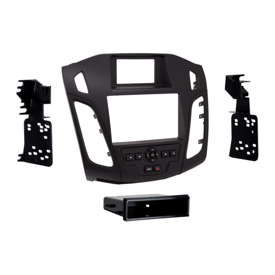
KIT COMPONENTS
• A) Radio trim panel • B) Radio brackets • C) Passenger airbag light panel • D) Pocket • E) (2) Carriage bolts • F) (2) Keps nuts
• G) (4) #8 x 3/8" Phillips screws • H) (2) Panel clips • I) Axxess interface and harnesses (not shown)
A
B
Metra. The World's Best Kits.
®
Ford Focus
(with 4.2" screen)
*Visit MetraOnline.com for up-to-date vehicle specific applications.
KIT FEATURES
• ISO DIN radio provision with pocket
• ISO DDIN radio provision
• Integrated controls for info center
• Includes Axxess interface and wiring
• Painted matte black
C
D
F
G
metraonline.com
2015-up*
E
H
© COPYRIGHT 2017 METRA ELECTRONICS CORPORATION
99-5843B
I N S TA L L AT I O N I N S T R U C T I O N S
TABLE OF CONTENTS
Dash Disassembly . .................................................2
Kit Preparation . ......................................................3
Kit Assembly
–ISO DIN radio provision with pocket . .................4
–ISO DDIN radio provision . ....................................4
Axxess interface installation . ................................5
Final assembly .......................................................8
WIRING & ANTENNA CONNECTIONS
Wiring Harness: Included with kit
Antenna Adapter: 40-EU10 (sold separately)
TOOLS REQUIRED
• Panel removal tool • Phillips screwdriver
• Socket wrench • T-25 Torx driver • Cutting tool
CAUTION!
All accessories, switches, climate
controls panels, and especially air bag indicator
lights must be connected before cycling the
ignition. Also, do not remove the factory radio
with the key in the on position, or while the
vehicle is running.
REV. 11/14/17 INST99-5843B
Advertisement
Table of Contents

Related Manuals for Metra Electronics 99-5843B


Summary of Contents for Metra Electronics 99-5843B
- Page 1 Also, do not remove the factory radio with the key in the on position, or while the vehicle is running. Metra. The World’s Best Kits. metraonline.com ® © COPYRIGHT 2017 METRA ELECTRONICS CORPORATION REV. 11/14/17 INST99-5843B...
- Page 2 DASH DISASSEMBLY 1. Unclip, unplug, and remove the trim 4. Remove (2) T-25 Torx screws from the panel with the passenger airbag light bottom of the radio panel. (Figure D) in it. Keep the airbag light for Kit 5. Unclip, unplug and remove the radio Preparation. (Figure A) control panel including the A/C vents. 2. Unclip and remove the trim panel (Figure E) around the shifter panel. (Figure B) 6. Remove (2) T-25 Torx screws securing 3. Remove (3) Phillips screws securing the radio, and (4) T-25 Torx screws the shifter panel, then unclip and slide securing the display and bracket, and (Figure A) (Figure D) then unplug and remove. (Figure F) the shifter panel toward the rear of the vehicle. (Figure C) Continue to Kit Preparation (Figure B) (Figure E) (Figure C) (Figure F) 1.800.221.0932 MetraOnline.com...
- Page 3 KIT PREPARATION 1. Unclip and remove the A/C vents from 4. Clip the A/C vents, removed from Step 1, the factory radio panel. (Figure A) onto the radio trim panel. (Figure D) 2. Remove the factory display from the Install the (2) panel clips, and the factory bracket assembly. (Figure B) factory passenger airbag light, to the passenger airbag light panel. (Figure E) 3. Cut and remove the (2) tabs on the bottom of the factory display. (Figure C) Continue to Kit Assembly (Figure A) (Figure D) (Figure B) (Figure E) Detail (Figure C) REV. 11/14/2017 INST99-5843B...
- Page 4 KIT ASSEMBLY ISO DIN radio provision with pocket ISO DDIN radio provision Secure the factory display to the radio Secure the factory display to the radio housing brackets with the supplied housing brackets with the supplied carriage bolts and Keps nuts. (Figure A) carriage bolts and Keps nuts. (Figure A) Detail Slide the radio into the radio bracket Detail assembly and secure with screws Secure the pocket to the radio supplied with the radio. (Figure B) housing bracket/display assembly with the (4) #8 x 3/8” Phillips screws Continue to Axxess interface supplied. (Figure B) installation Remove the metal DIN sleeve and trim (Figure A) (Figure A) ring from the aftermarket radio. Slide the radio into the radio bracket assembly and secure with screws supplied with the radio. (Figure B) Continue to Axxess interface installation (Figure B) (Figure B) 1.800.221.0932 MetraOnline.com...
-
Page 5: Table Of Contents
AXXESS INTERFACE INSTALLATION INTERFACE FEATURES TABLE OF CONTENTS Connections to be made ......................6-7 • Provides accessory power (12-volt 10-amp) Installing the interface .........................7 • Retains R.A.P. (retained accessory power) Initializing the interface .......................7 • Provides NAV outputs (parking brake, reverse, speed sense) Final assembly ..........................8 • Retains audio controls on the steering wheel Extra features ..........................8 • Retains SYNC Steering wheel control settings ....................9-11 • Designed for non-amplified models - L.E.D. feedback ...........................9 • Retains balance and fade - Changing radio type ........................9 • Micro “B” USB updatable - Remapping the steering wheel control buttons ..............10 - Dual assignment instructions (long button press) ............10-11 INTERFACE COMPONENTS - Resetting the interface . -
Page 6: Connections To Be Made
CONNECTIONS TO BE MADE From the 16-pin harness with stripped leads to the aftermarket radio: From the 5843 harness to the aftermarket radio: • Connect the Red wire to the accessory wire. • Connect the Black wire to the ground wire. • Connect the Blue/White wire to the amp turn on wire. • Connect the Yellow wire to the battery wire. • If the aftermarket radio has an illumination wire, connect the Orange/White wire to it. • Connect the Blue wire to the power antenna wire. • If the aftermarket radio has a mute wire and the vehicle is equipped with SYNC, connect • Connect the Green wire to the left rear positive speaker output. the Brown wire to it. If the mute wire is not connected, the radio will turn off when • Connect the Green/Black wire to the left rear negative speaker output. -
Page 7: Installing The Interface
CONNECTIONS TO BE MADE INSTALLING THE INTERFACE (CONT.) With the key in the off position: 3.5mm jack steering wheel control retention: • The 3.5mm jack is to be used to retain audio controls on the steering wheel. • Connect the 5843 harness into the interface, and then to the wiring harness in the vehicle. • For the radios listed below, connect the included female 3.5mm connector with stripped leads, • Connect the 16-pin harness with stripped leads into the interface. to the male 3.5mm SWC jack from the Interface. Any remaining wires tape off and disregard. • Connect the harness removed in step 6 of dash disassembly, back into the factory screen. • Eclipse: Connect the steering wheel control wire, normally Brown, to the Brown/White • Connect the harness removed in step 5 of dash disassembly, to the radio trim panel. wire of the connector. Then connect the remaining steering wheel control wire, normally Note: If retaining steering wheel controls, ensure the jack/wire is connected before proceeding Brown/White, to the Brown wire of the connector . onto the next step. -
Page 8: Final Assembly
FINAL ASSEMBLY EXTRA FEATURES Secure the assembly into the sub dash SYNC: using the factory hardware. • Change the source of the radio to AUX-IN; SYNC audio will start playing if SYNC has been activated. Reassemble the dash in the reverse order of disassembly using the • Listed below are the functions of the integrated buttons on the kit while using SYNC: 99-5843B trim panel instead of the • Arrow up—Channel up (only in USB mode) factory panel. • Arrow down—Channel down (only in USB mode) Install the passenger airbag light assembly into the 99-5843B radio • Enter—Selects current item on the screen trim panel. (Figure A) • Return/ESC—Exits to the previous screen Note: The integrated buttons on this kit (Figure A) are used to navigate the factory display above the radio. The button below the info button can be used to turn the factory screen on and off if desired. The remainder of the control functions are the same as factory was prior to aftermarket installation. 1.800.221.0932 MetraOnline.com... -
Page 9: Steering Wheel Control Settings
STEERING WHEEL CONTROL SETTINGS Attention: The Axxess Updater App can also be used to program the following (3) sub-sections L.E.D. feedback as well, pending that the interface has been initialized and programmed. The (18) Red L.E.D. flashes represent what brand radio the Interface believes it is connected to. Each flash represents a different radio manufacturer. For example, if you are installing a JVC Changing radio type radio, the Interface will flash (5) times. Following is a legend that dictates which manufacturer If the LED flashes do not match the radio you have connected, you must manually program the corresponds to which flash. Interface to tell it what radio it is connected to. L.E.D. feedback legend 1. After (3) seconds of turning the key on, press and hold the Volume-Down button on the 1st flash is for Eclipse (Type 1) † 10th flash is for Clarion (Type 2) † steering wheel until the L.E.D. in the Interface goes solid. 2nd flash is for Kenwood ‡ 11th flash is for Metra OE 2. Release the Volume-Down button; the L.E.D. will go out indicating we are now in 3rd flash is for Clarion (Type 1) † 12th flash is for Eclipse (Type 2) † Changing Radio Type mode. 4th flash is for Sony/Dual 13th flash is for LG 5th flash is for JVC 14th flash is for Parrot ** 3. Refer to the Radio Legend to know which radio number you would like to 6th flash is for Pioneer/Jensen 15th flash is for XITE have programmed. -
Page 10: Remapping The Steering Wheel Control Buttons
STEERING WHEEL CONTROL SETTINGS (CONT.) Radio legend Button assignment legend 1. Eclipse (Type 1) 6. Pioneer/Jensen 11. Metra OE 15. XITE 1. Volume-Up 6. Mute 11. Play/Enter 15. Fan-Up ** 2. Kenwood 7. Alpine 2. Volume-Down 7. Preset-Up 12. PTT 16. Fan-Down ** 12. Eclipse (Type 2) 16. Philips 3. Clarion (Type 1) 8. Visteon 3. Seek-Up/Next 8. Preset-Down (Push to Talk) * 17. Temp-Up ** 13. LG... -
Page 11: Resetting The Interface
STEERING WHEEL CONTROL SETTINGS (CONT.) 3. Press and release the Volume-Up button the number of times corresponding to the Resetting the Interface new button number selected. Refer to the Dual Assignment Legend. The L.E.D. will 1. With the radio on, turn the potentiometer: flash rapidly while the Volume-Up button is being pressed, and then go back to a solid Note: Before proceeding, remember the position the potentiometer is at. L.E.D. once released. Go to the next step once the Volume-Up button has been pressed the desired number of times. Turn left the LED will come on hold until the LED goes out Caution: If more than (10) seconds elapses between pressing the Volume-Up button, this Turn right the LED will come on hold until the LED goes out procedure will abort, and the L.E.D. will go out. Turn back left the LED will come on hold until the LED goes out 4. To store the long press button in memory, press the button that you assigned a long Turn right the LED will come on hold until the LED goes out press button to (the button held down in Step 2). The L.E.D. will now go off indicating Turn back left the LED will begin to flash rapidly the new information has been stored. Turn back to the initial position Note: These steps must be repeated for each button you would like to assign a dual purpose feature to. To reset a button back to its default state, repeat Step 1, and then press the Volume- The rapid flash means the interface is starting its re-programming process. - Page 12 Log onto www.installerinstitute.com or call 800-354-6782 for more information and take steps toward a better tomorrow. Metra recommends MECP certified technicians Metra. The World’s Best Kits. metraonline.com ® © COPYRIGHT 2017 METRA ELECTRONICS CORPORATION REV. 11/14/17 INST99-5843B...
Need help?
Do you have a question about the 99-5843B and is the answer not in the manual?
Questions and answers