Table of Contents
Advertisement
Available languages
Available languages
Quick Links
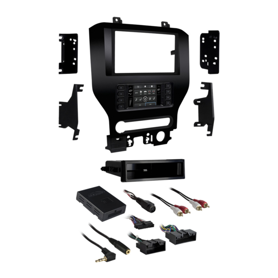
KIT COMPONENTS
• A) Radio trim panel with touchscreen display • B) Radio brackets • C) SYNC module brackets • D) Pocket • E) Engine start/stop circuit board and cover
• F) Engine start/stop trim • G) (4) #8 x 3/4" Phillips pan-head screws • H) (4) #8 x 3/8" Phillips truss-head screws • I) (6) #4 x 1/2" Phillips pan-head screws
• J) (4) Panel clips • K) USB cable • L) HVAC interface and wiring harness (not shown) • M) Antenna adapter (not shown)
A
B
G
The World's best kits.
®
Ford Mustang
Visit
MetraOnline.com
specific applications
KIT FEATURES
• ISO DIN radio provision with pocket
• ISO DDIN radio provision
• Touchscreen display for climate and personalization features
• Painted charcoal
C
D
H
I
MetraOnline.com
2015-2017
(with 4.2" screen)
for more detailed information about the product and up-to-date vehicle
E
F
J
K
© COPYRIGHT 2019 METRA ELECTRONICS CORPORATION
99-5838CH
I N S TA L L AT I O N I N S T R U C T I O N S
TABLE OF CONTENTS
Dash Disassembly .............................................. 2-4
Kit Preparation ....................................................5-7
Kit Assembly
–ISO DIN radio provision with pocket ..................8
–ISO DDIN radio provision .....................................8
Axxess Interface installation ............................9-18
Final Assembly ......................................................13
WIRING & ANTENNA CONNECTIONS
Wiring Harness: Axxess interface built
into touchscreen
Antenna Adapter: Included with kit
TOOLS REQUIRED
• Panel removal tool • Phillips screwdriver
• 9/32" socket wrench • Cutting tool
• Torx T-10 screwdriver
Attention!
Let the vehicle sit with the key
out of the ignition for a few minutes before
removing the factory radio. When testing the
aftermarket equipment, ensure that all factory
equipment is connected before cycling the
key to ignition.
REV. 10/28/20 INST99-5838CH
Advertisement
Chapters
Table of Contents

Related Manuals for Metra Electronics 99-5838CH


Summary of Contents for Metra Electronics 99-5838CH
- Page 1 When testing the aftermarket equipment, ensure that all factory equipment is connected before cycling the key to ignition. The World’s best kits. MetraOnline.com ® © COPYRIGHT 2019 METRA ELECTRONICS CORPORATION REV. 10/28/20 INST99-5838CH...
- Page 2 DASH DISASSEMBLY 1. Open the passenger door and remove the trim panel from the side of the dash. (Figure A) 2. Open the glove box and remove the trim panel on the right side. (Figure B) 3. Unclip and remove the trim/vent dash panel.
- Page 3 DASH DISASSEMBLY (CONT.) 4. Remove the rubber tray cover in front of the shifter, and then remove the (2) 9/32” screws exposed. (Figure D) 5. Unclip and remove the front side panels from each side of the center console. (Figure E) 6.
- Page 4 DASH DISASSEMBLY (CONT.) 7. Unclip the shifter trim bezel and slightly Ensure that the vehicle is completely off before pull it up to clear the center console trim proceeding onto the following (4) steps: bezel removal. 11. Remove the (4) 9/32” screws securing 8.
- Page 5 KIT PREPARATION 1. Cut and remove the shaded area from the sub-dash to allow clearance for the aftermarket radio. (Figure A) If SYNC is desired to be retained: 2. Attach the SYNC module brackets to the factory SYNC module using the (4) #8 x 3/4”...
- Page 6 KIT PREPARATION (CONT.) From the factory radio/climate control panel: 3. Remove the rubber button membrane from the back of the engine start/stop 1. Remove the (15) T-10 Torx screws securing switch panel. (Figure C) the plastic panel cover to the rear of the 4.
- Page 7 KIT PREPARATION (CONT.) 3. Insert the USB cable into the USB slot, To the 99-5838CH radio trim panel: through the rear. (Figure C) 1. Attach the engine start/stop trim, engine start/stop switch panel, and 4. Attach the (4) panel clips provided.
- Page 8 KIT ASSEMBLY ISO DIN radio provision with pocket ISO DDIN radio provision 1. Secure the radio brackets to the pocket 1. Secure the radio brackets to the radio using the (4) #8 x 3/8” Phillips truss-head using the screws supplied with the screws provided.
-
Page 9: Table Of Contents
AXXESS INTERFACE INSTALLATION INTERFACE FEATURES TABLE OF CONTENTS • Provides accessory power (12-volt 10-amp) Connections ..........................10-11 Installation ..........................12 • Retains R.A.P. (retained accessory power) Programming ..........................13 • Provides NAV outputs (parking brake, reverse, speed sense) Extra features (SYNC)........................13 • Retains audio controls on the steering wheel Touchscreen display operation ....................14-15 •... -
Page 10: Connections
CONNECTIONS From the 16-pin harness with stripped leads to the aftermarket radio: From the 5838 harness to the aftermarket radio: • Connect the Red wire to the accessory wire. • Connect the Black wire to the ground wire. • If the aftermarket radio has an illumination wire, connect the Orange/White wire to it. •... - Page 11 CONNECTIONS (CONT.) 3.5mm jack - steering wheel control retention: 12-pin backup camera harness: The 3.5mm jack is to be used to retain audio controls on the steering wheel control. There are two different methods for connecting the factory backup camera. For the radios listed below: Connect the included female 3.5mm connector with stripped leads, to •...
-
Page 12: Installation
INSTALLATION It is highly advisable to read the following steps beforehand, to ensure a clear understanding of HVAC interface what is to be expected. The following steps must be done in the order that they are numbered. 6. Connect the HVAC interface harness into the HVAC interface, and then to the With the vehicle completely off: wiring harnesses in the vehicle. -
Page 13: Programming
4. Cycle the key off. If the driver’s door is closed, open and close the door. Cycle the key back on. If the vehicle is equipped with SYNC, the 99-5838CH can retain this feature. 5. Test all functions of the installation for proper operation, before reassembling the dash. -
Page 14: Touchscreen Display Operation
TOUCHSCREEN DISPLAY OPERATION Climate Control screen • This is the climate control screen which will be displayed on the touchscreen display. This is considered the Main Menu. • Disregard the upper left tab with (3) arrows, it will not be used in this application. •... - Page 15 TOUCHSCREEN DISPLAY OPERATION (CONT.) Configuration Settings • Backlight • Steering Wheel Controls • Remap Buttons – For remapping the steering wheel control buttons • For controlling the color of the buttons and back-light intensity. • Dual Assign – For dual assigning the steering wheel control buttons (long button press) •...
-
Page 16: Steering Wheel Control Settings
STEERING WHEEL CONTROL SETTINGS Remap Buttons Dual Assign • The interface has the ability to change the button assignment for the steering wheel • The interface has the capability to assign two functions to a single button, except control audio buttons, except Volume-Up and Volume-Down. Follow the Volume-Up and Volume-Down. - Page 17 STEERING WHEEL CONTROL SETTINGS (CONT.) Select Radio * Note: If the interface shows an Alpine radio, and you do not have an Alpine radio, that means the interface does not detect a radio connected it, i.e., an open connection. Verify that the 3.5mm jack is connected to the correct steering wheel jack/wire in the radio.
-
Page 18: Troubleshooting
TROUBLESHOOTING Resetting the interface Option # 1 1. With everything connected and the car running. 2. Hold the bottom (2) buttons for 3 seconds, then release. (Figure A) (The screen will turn black and then put you in the vehicle selection screen) 3. - Page 19 REV. 10/28/2020 INST99-5838CH...
- Page 20 Log onto www.installerinstitute.com or call 800-354-6782 for more information and take steps toward a better tomorrow. Metra recommends MECP certified technicians The World’s best kits. MetraOnline.com ® © COPYRIGHT 2019 METRA ELECTRONICS CORPORATION REV. 10/28/20 INST99-5838CH...
- Page 21 Además, no quite el radio de fábrica con la llave en la posición o de encendido ni con el vehículo funcionando. The World’s best kits. MetraOnline.com ® © COPYRIGHT 2020 METRA ELECTRONICS CORPORATION REV. 10/28/20 INST99-5838CH...
- Page 22 DESMONTAJE DEL TABLERO 1. Abra la puerta del pasajero y quite el panel de la moldura en el lado del tablero. (Figura A) 2. Abra la guantera y quite el panel de la moldura en el lado derecho. (Figura B) 3.
- Page 23 DESMONTAJE DEL TABLERO (CONT.) 4. Quite la cubierta de la charola de caucho frente a la palanca de velocidades y luego quite los (2) tornillos de 9/32” que quedan a la vista. (Figura D) 5. Desenganche y quite los paneles laterales frontales de cada lado de la consola central.
- Page 24 DESMONTAJE DEL TABLERO (CONT.) 7. Desenganche el bisel de la moldura Asegúrese de que el vehículo esté de la palanca de velocidades y jálela completamente apagado antes de pasar a los siguientes (3) pasos: ligeramente hacia arriba para poder quitar la bisel central de la consola 11.
- Page 25 PREPARACIÓN DEL KIT 1. Corte y quite el área sombreada del sub tablero para hacer espacio para el radio de mercado secundario. (Figura A) Si se desea retener SYNC: 2. Sujete los soportes del módulo SYNC al módulo SYNC de fábrica usando los (4) tornillos Phillips #8 de 3/8”...
- Page 26 PREPARACIÓN DEL KIT (CONT.) Del panel del radio/control del clima de 4. Quite el panel del interruptor de fábrica: encendido/apagado del motor. (Figura D) 1. Quite los (15) tornillos Torx T-10 sujetando la cubierta del panel de 5. Oprima hacia adentro en las (2) plástico a la parte trasera del panel y pestañas de retención dentro de la luego quite.
- Page 27 PREPARACIÓN DEL KIT (CONT.) 3. Inserte el cable USB en la ranura USB, Al panel de la moldura del radio 99-5838CH: por la parte trasera. (Figura C) 1. Una la moldura de encendido/apagado 4. Conecte los (4) ganchos para panel del motor, panel del interruptor de suministrados.
- Page 28 ENSAMBLE DEL KIT Provisión de radio ISO DIN con cavidad Provisión de radio ISO DDIN 1. Fije los soportes del radio usando los 1. Fije los soportes de radio al bolsillo tornillos que vienen con el radio. utilizando los (4) tornillos Phillips # 8 x (Figura A) 3/8 ”provistos.
- Page 29 INSTALACIÓN DE LA INTERFASE AXXESS INSTALACIÓN DE LA INTERFAZ AXXESS INDICE • Provee corriente de accesorio (12 voltios 10 amperes) Conexiones ..........................10-12 Instalación ........................... 12 • Retiene R.A.P. (corriente de accesorio retenida) Programación ..........................13 • Proporciona salidas de NAV (freno de mano, reversa, sensor de velocidad) Características adicionales (SYNC) ....................13 •...
-
Page 30: Conexiones
CONEXIONES Del arnés de 16 pins con conectores pelados al radio de mercado secundario: Desde el arnés 5838 al radio de mercado secundario: • Conecte el cable negro al cable de tierra. • Conecte el cable rojo al cable de accesorios. •... - Page 31 CONEXIONES (CONT.) La retención del control en volante con conector de 3.5 mm Nota: Después de haber programado la interfaz al vehículo, haga referencia al manual provisto con el radio para asignar los botones SWC. Contacte al fabricante del radio para El conector de 3.5 mm se debe usar para retener los controles de audio en el control del volante.
-
Page 32: Instalación
INSTALACIÓN Se recomienda de gran manera que lea antes los siguientes pasos para asegurar que entienda Interfaz HVAC bien lo que se espera. Los siguientes pasos deben seguirse en el orden en que están numerados. 6. Conecte el arnés de la interfaz HVAC en la interfaz HVAC y luego a los arneses de cableado Con el vehículo completamente apagado: en el vehículo. -
Page 33: Programación
SYNC: arneses 5838 del puerto “A” en la pantalla táctil. Revise todas las conexiones, vuelva a Si el vehículo está equipado con SYNC, el 99-5838CH puede conservar esta función. conectar el arnés a la pantalla táctil e inténtelo de nuevo. -
Page 34: Operación De La Pantalla Táctil
OPERACIÓN DE LA PANTALLA TÁCTIL Pantalla de control HVAC • Esta es la pantalla de control HVAC que se mostrará en la pantalla táctil. Esto se considera como la pantalla principal. • Ignore la pestaña superior izquierda con (3) flechas; no se utilizará en esta aplicación. •... - Page 35 OPERACIÓN DE LA PANTALLA TÁCTIL (CONT.) Pantalla de Configuraciones • Controles en el volante • Botones de reubicación: para reubicar los botones del control en el volante • Doble asignación: para doble asignación de los botones de control en el volante (presionar el botón por largo tiempo) •...
-
Page 36: Configuración Del Control En El Volante
CONFIGURACIÓN DEL CONTROL EN EL VOLANTE Pantalla para reubicar el botón Pantalla de doble asignación • La interfaz tiene la capacidad de cambiar la asignación de botón para los botones de audio del • La interfaz tiene la capacidad de asignar dos funciones a un solo botón, excepto Subir control en el volante, excepto para Subir volumen y Bajar volumen. - Page 37 CONFIGURACIÓN DE CONTROL EN VOLANTE (CONT.) Seleccionar la pantalla del radio * Nota: Si la interfaz muestra un radio Alpine y no tiene un radio Alpine, eso significa que la interfaz no detecta un radio conectado a él; es decir, una conexión abierta. Verifique que el conector de 3.5 mm esté conectado al conector/cable correcto del volante en el radio. ** Nota: Se requiere el AX-SWC-PARROT (se vende por separado). Además, el radio Parrot debe estar actualizado a la versión de software 2.1.4 o posterior mediante www.parrot.com. † Nota: Si tiene un radio Clarion y los controles en el volante no funcionan, cambie el tipo de radio al otro tipo de radio Clarion; haga lo mismo con Eclipse. ‡ Nota: Si tiene un radio Kenwood y la pantalla táctil muestra un radio JVC, cambie el tipo de radio a Kenwood. • Para mostrar qué marca de radio se “detecta automáticamente” a la interfaz, oprima el botón “Autodetect”.
-
Page 38: Resolución De Problemas
RESOLUCIÓN DE PROBLEMAS Restablecimiento de la interfaz Opción 1 1. Con todo conectado y el coche en marcha. 2. Mantenga presionados los botones inferiores (2) durante 3 segundos y luego suéltelos. (Figura A) (La pantalla se volverá negra y luego lo pondrá en la pantalla de selección de vehículo) 3. - Page 39 REV. 10/28/2020 INST99-5838CH...
- Page 40 800-354-6782 para obtener más información y avance hacia un futuro mejor. Metra recomienda técnicos con certificación del Programa de Certificación en Electrónica Móvil (Mobile Electronics Certification Program, MECP). The World’s best kits. MetraOnline.com ® © COPYRIGHT 2020 METRA ELECTRONICS CORPORATION REV. 10/28/20 INST99-5838CH...
Need help?
Do you have a question about the 99-5838CH and is the answer not in the manual?
Questions and answers