Advertisement
Quick Links
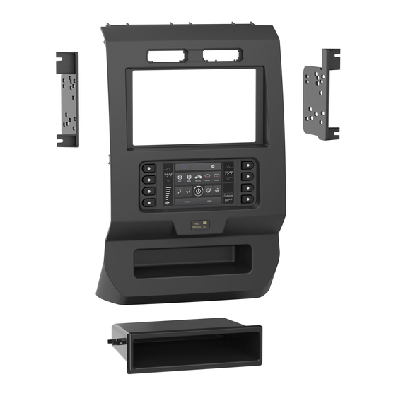
KIT COMPONENTS
• A) Radio trim panel with touchscreen display • B) Radio brackets • C) SYNC
• F) (4) #4 x 1/2" Phillips pan-head screws • G) (7) Panel clips • H) HVAC interface and wiring harness (not shown)
B
A
The World's best kits.
®
Ford F-150 2015-up
KIT FEATURES
• ISO DIN radio provision with pocket
• ISO DDIN radio provision
• Painted Charcoal
• Touchscreen display for climate and personalization features
Note: Does not work with Sony amplified systems.
Note: Does not support Pro Trailer Backup Assist™, 10-way power
driver and passenger seats with power lumbar, and massage seats.
®
module brackets • D) Pocket • E) (4) #8 x 3/8" Phillips truss-head screws
C
D
E
F
G
99-5834CH
I N S TA L L AT I O N I N S T R U C T I O N S
TABLE OF CONTENTS
Dash Disassembly . ..............................................2-3
Kit Preparation . ......................................................4
Kit Assembly
– ISO DIN radio provision with pocket . ................5
– ISO DDIN radio provision . ...................................5
Axxess Interface Installation . ...........................6-15
WIRING & ANTENNA CONNECTIONS
Wiring Harness: Axxess interface and wiring
harness included
Antenna Adapter: 40-EU10 (sold separately)
TOOLS REQUIRED
• Panel removal tool • Phillips screwdriver
• 9/32" Socket wrench • Cutting tool
CAUTION!
All accessories, switches, climate
controls panels, and especially air bag indicator
lights must be connected before cycling the
ignition. Also, do not remove the factory radio
with the key in the on position, or while the
vehicle is running.
Advertisement

Related Manuals for Metra Electronics 99-5834CH


Summary of Contents for Metra Electronics 99-5834CH
- Page 1 99-5834CH I N S TA L L AT I O N I N S T R U C T I O N S Ford F-150 2015-up TABLE OF CONTENTS Dash Disassembly ..........2-3 Kit Preparation ............4 KIT FEATURES Kit Assembly • ISO DIN radio provision with pocket • ISO DDIN radio provision – ISO DIN radio provision with pocket .
- Page 2 DASH DISASSEMBLY 1. For vehicles with a center channel Ensure that the vehicle is completely off before speaker: Unclip and remove the speaker proceeding onto the following (5) steps grille in the center of the dash above the 4. Unclip, unplug, and remove the radio/ radio/climate control panel, and then climate control panel. remove the (2) 9/32” screws exposed. 5. Remove the 9/32” screws securing the (Figure A) display screen; qty. (4) for the 4.2-inch 2. For vehicles without a center channel (Figure A) display screen models, qty. (6) for 8-inch speaker: Remove the rubber pad in the...
- Page 3 DASH DISASSEMBLY 6. For models with a 4.2-inch display 8. For models equipped with a factory ® screen and SYNC : Remove the (2) 9/32” backup camera: Remove the (3) 10mm ® screws securing the SYNC module, then nuts securing the camera module, move unplug and remove. (Figure F) the module down onto the lower stud, and then re-secure using just 7. Remove the (4) 9/32” screws securing (1) 10mm nut. (Figure H) the radio chassis, then unplug and remove. (Figure G) Continue to Kit Preparation (Figure H) (Figure F) (Figure G)
- Page 4 SYNC is desired to be retained: 1. Unclip and remove the hazard switch 1. Remove the (4) 9/32’ screws securing and traction control buttons. ® the brackets from SYNC module. 2. Attach the SYNC ® module brackets to To the 99-5834CH radio trim panel: the SYNC ® module using the (4) (Figure C) 1. Attach the hazard switch and traction #8 x 1/2” Phillips pan-head screws control buttons. (Figure C) provided. (Figure A) 2. Attach the (7) panel clips provided. 3. Secure the module into the lower (Figure D)
- Page 5 KIT ASSEMBLY ISO DIN radio provision with pocket ISO DDIN radio provision 1. Attach the pocket to the radio brackets 1. Attach the radio brackets to the radio using the (4) supplied #8 x 3/8” Phillips using screws supplied with the radio. truss-head screws. (Figure A) (Figure A) 2. Remove the metal DIN sleeve and trim ring from the aftermarket radio. 3. Slide the radio into the completed assembly, and then secure it to the assembly using screws supplied with the radio. (Figure B) (Figure A) (Figure A) (Figure B)
-
Page 6: Table Of Contents
AXXESS INTERFACE INSTALLATION INTERFACE FEATURES TABLE OF CONTENTS • Provides accessory power (12-volt 10-amp) Connections to be made ......................7-8 • Retains R.A.P. (retained accessory power) Installing the interface ......................... 9 • Provides NAV outputs (parking brake, reverse, speed sense) Initializing the interface ......................10 • Retains audio controls on the steering wheel Final assembly ..........................10 ® • Retains SYNC (4.2-inch display screen models only) Touchscreen display operation ....................11-12 • Retains the factory backup camera Steering wheel control settings .................... 13-14 • Retains balance and fade • Micro “B” USB updatable INTERFACE COMPONENTS TOOLS REQUIRED • Axxess interface (built into the touchscreen display) -
Page 7: Connections To Be Made
CONNECTIONS TO BE MADE From the 16-pin harness with stripped leads to the aftermarket radio: From the 5834 harness to the aftermarket radio: • Connect the Red wire to the accessory wire. • Connect the Black wire to the ground wire. • If equipped with a factory subwoofer, connect the Blue/White wire to the amp turn on wire. • Connect the Yellow wire to the battery wire. • If the aftermarket radio has an illumination wire, connect the Orange/White wire to it. • Connect the Green wire to the left rear positive speaker output. • If the aftermarket radio has a mute wire, and the vehicle is equipped with SYNC ® , connect • Connect the Green/Black wire to the left rear negative speaker output. the Brown wire to it. If the mute wire is not connected, the radio will turn off when SYNC ®... - Page 8 CONNECTIONS TO BE MADE (CONT.) 3.5mm jack steering wheel control retention: Backup camera harness: • The 3.5mm jack is to be used to retain audio controls on the steering wheel control. For models with a 4.2-inch display screen: • For the radios listed below, connect the included female 3.5mm connector with stripped leads, to • Use the 12-pin backup camera harness. the male 3.5mm SWC jack from the 5834 harness. Any remaining wires tape off and disregard: For models with an 8-inch display screen: • Eclipse: Connect the steering wheel control wire, normally Brown, to the Brown/White wire of • Use the 54-pin backup camera harness. the connector. Then connect the remaining steering wheel control wire, normally Brown/White, to the Brown wire of the connector .
-
Page 9: Installing The Interface
INSTALLING THE INTERFACE It is highly advisable to read the following steps beforehand, to ensure a clear understanding of HVAC interface what is to be expected. The following steps must be done in the order that they are numbered. 6. Connect the HVAC interface harness into the HVAC interface, and then to the wiring harnesses in the vehicle. These harnesses are the ones removed in step 4 With the vehicle completely off: of dash disassembly. Touchscreen display Note: Disregard the 10-pin harness, it will not be used in this application. 1. Connect the 16-pin harness with stripped leads into port “B” in the touchscreen display. 7. Connect the 4-pin flat to 4-pin stacked harness into the HVAC interface, and then to 2. Connect the 5834 harness to the wiring harnesses in the vehicle. These harnesses are the passenger airbag light assembly. the ones removed in step 7 of dash disassembly. Then insert the 5834 harness into port 8. Connect the male DIN connector with a 6-pin harness, to the female DIN jack from the “A” in the touchscreen display. But do not install this harness until exactly before step 1 5834 harness. It would be best to tape or heat shrink this connector to prevent it from of “Initializing the Interface”. This is a timed process. being disconnected. 3. Connect the 4-pin harness with yellow RCA jacks into port “C” in the a. Then connect the 6-pin harness into the HVAC interface. touchscreen display. b. Disregard the Red wire, it will not be used in this application. 4. Disregard ports “D” and “E”, they will not be used in this application. 9. -
Page 10: Initializing The Interface
INITIALIZING THE INTERFACE FINAL ASSEMBLY Attention! If the interface loses power for any reason, the following steps will need to be 1. Secure the completed assembly into the upper dash using the factory hardware removed in performed again. step 5 of dash disassembly. 1. Refer to step 2 of “Installing the interface”. 2. Snap the radio trim panel with touchscreen display over the completed assembly, and then reassemble the dash in reverse order of disassembly. 2. Press the push-to-start button to start the vehicle. 3. Program the kit: a. Once the touchscreen display loads up, select the vehicle type; “Ford F-150”. b. Wait until the radio comes on, and the touchscreen display shows “SWC Configured*”. This process may take up to 3 minutes. Note: If the touchscreen display does not load up, or the radio doesn’t come on within 3 minutes, and/or the touchscreen display does not show “SWC Configured*”, turn the vehicle off and disconnect the 5838 harnesses from port “A” in the touchscreen display. Check all the connections, reconnect the harness into the touchscreen display, and then try again. * For models with steering wheel controls. 4. Test all functions of the installation for proper operation, before reassembling the dash. -
Page 11: Touchscreen Display Operation
TOUCHSCREEN DISPLAY OPERATION HVAC Control screen • This is the HVAC control screen which will be displayed on the touchscreen display. This is considered the main screen. • The upper left tab with (3) arrows will take you to the Heated/Cooled seats screen, if applicable. Note: This screen will also include Heated Steering if applicable. • The upper right tab with the gear icon will take you to the Configuration Settings screen. • Auto climate models: The climate controls will function in the same manner that they did with the factory climate controls. Manual climate controls • Manual climate models: The climate controls will function in the same manner that they did with the factory climate controls, yet via touchscreen buttons instead. The temperature control will display a numerical scale, with “LO” being the coldest, and “HI” being the hottest: LO / 1-9 / HI Note: The “Info” button will only be shown if SYNC is to be retained. Continued on the next page Automatic climate controls... - Page 12 TOUCHSCREEN DISPLAY OPERATION (CONT.) Configuration Settings screen • Steering Wheel Controls • Remap Buttons – For remapping the steering wheel control buttons • Dual Assign – For dual assigning the steering wheel control buttons (long button press) • Select Radio – For auto detecting the radio, or changing the radio type • System Configuration • Firmware version Touchscreen calibration • Backlight • Press and hold the upper two soft buttons on either side of the touchscreen for 10 seconds. • Four slide bars control the color of the buttons and the back-light intensity: • A screen will pop up asking for you to press the target in the screen. Red / Green / Blue / Backlight • After pressing the target with your finger, the calibration process will be complete, and the • Backup Camera screen will disappear. • Enable – Enables the backup camera image to the touchscreen display Continued on the next page • Disable – Disables the backup camera image to the touchscreen display (default)
-
Page 13: Steering Wheel Control Settings
STEERING WHEEL CONTROL SETTINGS Select Radio screen * Note: If the interface shows an Alpine radio, and you do not have an Alpine radio, that means the interface does not detect a radio connected it, i.e., an open connection. Verify that the 3.5mm jack is connected to the correct steering wheel jack/wire in the radio. ** Note: The AX-SWC-PARROT is required (sold separately). Also, the Parrot radio must be updated to rev. 2.1.4. † Note: If you have a Clarion radio and the steering wheel controls do not work, change the radio type to the other Clarion radio type; same for Eclipse. ‡ Note: If you have a Kenwood radio and the touchscreen display shows a JVC radio, change the radio type to Kenwood. • To show which brand radio is “auto detected” to the interface, press the “Autodetect” Continued on the next page button. The radio detected will have a filled in circle. If the incorrect radio is shown, select the proper radio. • Following is a list of radio manufacturers that the interface presently acknowledges. Others may be added at a later date. Universal “2 or 3 wire” radios can show up as any of these radio manufacturers. Eclipse (Type 1) † Pioneer/Jensen Clarion (Type 2) † Parrot ** Kenwood ‡ Alpine * Metra OE XITE Clarion (Type 1) †... - Page 14 STEERING WHEEL CONTROL SETTINGS (CONT.) Remap Button screen Dual Assign screen • The interface has the ability to change the button assignment for the steering wheel • The interface has the capability to assign two functions to a single button, except Volume- control audio buttons, except Volume-Up and Volume-Down. Follow the prompts on the Up and Volume-Down. Follow the prompts on the touchscreen display to program the touchscreen display to remap the steering wheel control audio button(s) to your liking. button(s) to your liking. Note: The aftermarket radio may not have all of these commands. Please refer to Note: Seek-Up and Seek-Down come programmed as Preset-Up and Preset-Down the manual provided with the radio, or contact the radio manufacturer, for specific for a long button press. commands recognized by that particular radio.
Need help?
Do you have a question about the 99-5834CH and is the answer not in the manual?
Questions and answers