
Subscribe to Our Youtube Channel
Related Manuals for KBR multisio 5D6-ESBS-5DI6RO1DO


Summary of Contents for KBR multisio 5D6-ESBS-5DI6RO1DO
- Page 1 Operating Instructions Technical Parameters multisio 5D6-ESBS-5DI6RO1DO Electronic impuls metering device...
- Page 2 KBR GmbH Am Kiefernschlag 7 D-91126 Schwabach T +49 (0) 9122 6373-0 F +49 (0) 9122 6373-83 E info@kbr,de www.kbr.de...
- Page 3 Preface Dear Customer We would like to thank you for choosing a KBR GmbH quality product. In order to familiarize yourself with the operation and programming of the device and always be able to use the whole functionality of this high-quality product, we recommend that you read this manual thoroughly.
- Page 4 The specifications made in this manual are checked on a regular basis, necessary corrections are included in the next revision. We appreciate your corrections and comments. © KBR-GmbH Subject to change Page II von IV...
- Page 5 Safety Precautions General Safety Precautions In order to prevent operating errors, handling of the device is kept as simple as possible. This way, you will be able to use the device very soon. In your own interest, however, you should read the following safety precautions carefully. Warning During installation, the applicable DIN / VDE regulations must be obser- ved!
- Page 6 Product Liability / Disposal Product Liability With these product, you have acquired a quality product. In its manufacture, only components of the highest reliability and quality were used. Each device is subject to long-term testing before it is delivered. For information on product liability, please refer to our General Terms and Conditions for electronic devices. The warranted properties of the device apply only if it is operated in accordance with its intended use! Disposal Please dispose of defective, outdated or no longer used devices properly.
-
Page 7: Table Of Contents
Table of Contents Device memory, battery buffered ............3 Explanation of terms ................4 Implementation / range of function ............4 Connection of the multisio 5D6-ESBS-5DI6RO1DO ......9 Installation and Assembly ................... 9 Connection diagram ..................... 9 Terminal assignment ..................10 Commissioning .................. - Page 8 Operating instructions multisio 5D6-ESBS-5DI6RO1DO Appendix ....................18 General technical data of modules ..............18 Digital input module multisio 2D2-4DI ..............19 9.2.1 Digital input module connection chart ..............19 9.2.2 Function of the scan button ..................19 9.2.3 Digital input module LED display ................20 9.2.4...
-
Page 9: Device Memory, Battery Buffered
Operating instructions multisio 5D6-ESBS-5DI6RO1DO Device memory, battery buffered The device has an internal data memory, battery-buffered to preserve long-term data. This support battery (e.g. Varta CR 2032) is not installed in the device on delivery, to prevent the battery from losing its charge, but is included in the delivery. -
Page 10: Explanation Of Terms
5D6-ESBS-5DI6RO1DO can be used to monitor errors and for example passed on to a central process control (selectable via a KBR eBus NC or NO contact). The addi- tionally available five floating relay outputs can be assigned to KBR eBus relay groups and used as NC or NO contacts (selectable via KBR eBus). - Page 11 The module evaluates the measured values of the temperature sensors connected to terminals 70 and 71, etc. The module can be addressed by the master device multisio 5D6-ESBS-5DI6RO1DO via the module bus interface. The master has to configure the module and read out the data recorded by the module for further processing.
- Page 12 The alarm relay switches on at 50°C and off at 45°C The module can be addressed by the master device multisio 5D6-ESBS-5DI6RO1DO via the module bus interface. The master has to configure the module and read out the data recorded by the module for further processing.
- Page 13 Two-tariffs counter function (HT/LT) The consumption during the various tariff periods is stored separately. Switching between the tariff periods is done either by a digital input, the KBR eBus (centrally from the Multimaster or the PC), or through the internal clock.
- Page 14 For example, the tariff switch signal of the energy supplier counter can be connected here. Tar- iff switching can also be controlled centrally via the KBR eBus as well as via the internal clock (see Chapter Two tariff counter function).
-
Page 15: Connection Of The Multisio 5D6-Esbs-5Di6Ro1Do
Operating instructions multisio 5D6-ESBS-5DI6RO1DO Connection of the multisio 5D6-ESBS-5DI6RO1DO Installation and Assembly The housing of the multisio 5D6-ESBS-5DI6RO1DO has been designed for wall mounting on a 35 mm DIN rail. The module is snapped on the mounted DIN rail. Caution The control voltage of the device must be protected by means of a back-up fuse. -
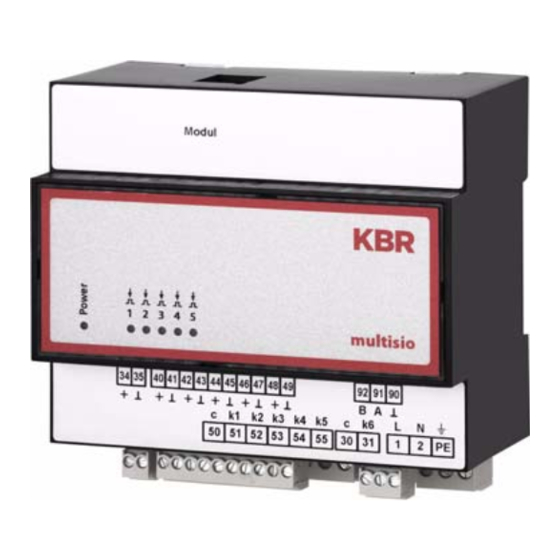
Page 16: Terminal Assignment
A floating contact of a pulse generator can be connected to this input Terminal 92 (B) Bus connection 91 (A) For communication at the KBR eBus 90 (earth): Module bus connection For communication with expansion modules Page 10 of 35... -
Page 17: Commissioning
3 seconds. The LEDs flash. During this phase, it is possible to assign an address via the KBR eBus PC software. Details of this can be found in the user manual for the corresponding software. After the address has been successfully assigned, the device goes into normal operation. -
Page 18: Basic Configuration When Delivered
6.1.2 Cycle memory The multisio 5D6-ESBS-5DI6RO1DO has a cycle memory that can record max. 5 x 3840 entries, depending on the measuring period selected by the user (possible period values 60 / 30 / 15 / 1 minutes). This means that a period of 60 min. results in a storage duration of 160 days max. -
Page 19: Event Memory
The measuring period synchronization is dependent on the energy form of the sync input on the multisio 5D6-ESBS-5DI6RO1DO and on the energy form of the individual inputs. This means that for ex- ample only those inputs that have the same energy form as the sync inputs on the device are synchronized. -
Page 20: Synchronization By The Kbr Ebus
LT has been switched, instead of waiting until the end of the measuring period. Tariff switching is carried out via a telegram created either by the computer or by the MULTIMASTER and sent via the KBR eBus to the se- lected recipients. -
Page 21: Technical Data
Operating instructions multisio 5D6-ESBS-5DI6RO1DO Technical data Operating and display elements Operation Pushbutton for reset and scan mode (accessible after removal of housing lid) Control display 6 green LEDs: 5 x input status, 1 x operating status Device memory Main data and program memory... -
Page 22: Hardware Outputs
Hardware outputs Interface Serial interface RS-485 for connection to the KBR eBus; a max. of 32 devices per bus seg- ment, up to 1000 m without bus amplifier if cables suitably laid, for additional information see installation guidelines KBR eBus... -
Page 23: Environmental Conditions / Electrical Safety
Windows® software, all bus devices can be configured and visualized. We will be glad to pro- vide information on which other devices you can connect to the KBR eBus and on the functions of our software. Information on the structure and the technical parameters of the KBE eBUS can be found in our installation guide for the KBR eBus. -
Page 24: Appendix
24VDC / approx. 2W Connection Modular socket contact RJ12:6P6C Module bus interface: Serial port RS-485 Module bus connection RJ12 for ready-made KBR system cable, max. length 30 m if cables suitably laid Transmission speed 38400 bps Bus protocol KBR-module bus Mechanical data:... -
Page 25: Digital Input Module Multisio 2D2-4Di
Operating instructions multisio 5D6-ESBS-5DI6RO1DO multisio 2D2-4DI Digital input module 9.2.1 Digital input module connection chart Terminal assignment Terminal 50: Digital input 1 + Terminal 51: Digital input 1 - Terminal 52: Digital input 2 + Terminal 53: Digital input 2 -... -
Page 26: Digital Input Module Led Display
LED is switched on. If the input is passive, the LED is switched off. All 4 input LEDs flash in the KBR eBus scanning mode. In the module detection mode, a running light is emitted with the input LEDs. -
Page 27: Function Of The Dip Switches
Operating instructions multisio 5D6-ESBS-5DI6RO1DO 9.2.4 Function of the DIP switches Manual operation: Each input can be individually set to manual operation. If the DIP switch of a channel is set to "OFF", the input state is accepted. If the DIP switch of a channel is set to "ON", the input state is set to active, irrespective of... -
Page 28: Temperature Input Module Multisio 2D2-4Ti
Module bus / supply voltage Temperature 9.3.2 module LED display All 4 input LEDs flash in the KBR eBus scanning mode. In the module detection mode, a running light is emitted with the input LEDs. LED1 for: Input 1 LED2 for:... -
Page 29: Function Of The Scan Button
When switching DIP switches S1 to S4 from ON to OFF the connection lead of the corresponding input is calibrated. For the calibration an adapter (obtained from KBR) is connected instead of the sensor. Version 5.00 Page 23 of 35... - Page 30 Operating instructions multisio 5D6-ESBS-5DI6RO1DO Module-specific technical data: Hardware inputs: 4 Temperature inputs Plug-in terminal 8-pin For sensor PT-1000 Measuring range Design 1 -20°C to +80°C +/- 1°C see nameplate Design 2 -40°C to + 40°C +/- 1°C Display 4x message...
-
Page 31: Analog Input Module Multisio 2D2-4Ai
Module bus / supply voltage Analog input 9.4.2 module LED display All 4 input LEDs flash in the KBR eBus scanning mode. In the module detection mode, a running light is emitted with the input LEDs. LED1 for: Input 1... -
Page 32: Function Of The Scan Button
Operating instructions multisio 5D6-ESBS-5DI6RO1DO 9.4.3 Function of the scan button Note If the scan button is briefly pressed, the module will change to scanning mode. Switch setting in illustration = OFF = white = grey 9.4.4 Function of the DIP switch... -
Page 33: Current Measuring Module Multisio 1D2-4Ci
The current inputs of the module are not electrically isolated from each other! 9.5.2 Current measuring module LED display In KBR eBus scanning mode, the Power LED flashes quickly, in the detection mode slowly. The LEDs are lit up permanently in normal mode. Power - LED: Operating voltage Version 5.00... -
Page 34: Function Of The Scan Button
Operating instructions multisio 5D6-ESBS-5DI6RO1DO 9.5.3 Function of the scan button Note If the scan button is briefly pressed (until all LEDS briefly light up), the module will change to scanning mode. Module-specific technical data: Hardware inputs: 4 current measuring inputs... -
Page 35: Temperature Module Multisio 2D2-1Ti2Ro
The relay outputs of the module are designed as floating outputs. 9.6.2 Temperature module LED display All 4 input LEDs flash in the KBR eBus scanning mode. In the module detection mode, a running light is emitted with the input LEDs. The displays are:... -
Page 36: Function Of The Scan Button
Operating instructions multisio 5D6-ESBS-5DI6RO1DO 9.6.3 Function of the scan button Note If the scan button is briefly pressed (until all LEDS briefly light up), the module will change to scanning mode. Switch setting in illustration: OFF = white ON = grey 9.6.4... -
Page 37: Relay Output Module Multisio 2D2-4Ro
LED is switched on. If the output is passive, the LED is switched off. All 4 output LEDs flash in the KBR eBus scanning mode. In the module detection mode, a running light is emitted with the output LEDs. -
Page 38: Function Of The Scan Button
Operating instructions multisio 5D6-ESBS-5DI6RO1DO 9.7.3 Function of the scan button Note If the scan button is briefly pressed, the module will change to scanning mode. Switch setting in illustration: OFF = white ON = grey 9.7.4 Function of the DIP switch Manual operation: It is possible to set every output to manually active. -
Page 39: Digital Output Module Multisio 2D2-4Do
9.8.2 Digital output module LED display All 4 input LEDs flash in the KBR eBus scanning mode. In the module detection mode, a running light is emitted with the output LEDs. A flashing LED indicates that the corresponding digital output is switched to manual operation. -
Page 40: Function Of The Scan Button
Operating instructions multisio 5D6-ESBS-5DI6RO1DO 9.8.3 Function of the scan button Note If the scan button is briefly pressed, the module will change to scanning mode. Switch setting in illustration: OFF = white ON = grey 9.8.4 Function of the DIP switch Manual operation: It is possible to set every output to manually active. - Page 41 Operating instructions multisio 5D6-ESBS-5DI6RO1DO Module-specific technical data: Hardware outputs: 4 Digital outputs compatible max. 35V / 50mA Plug-in terminal 8-pin Display 4x message 1x operational display Operating unit DIP switch 1x 8-channel, output configuration Buttons Scan button - module bus Version 5.00...
- Page 42 ERKLÄRUNG DER KONFORMITÄT DECLARATION OF CONFORMITY DÉCLARATION DE CONFORMITÉ KBR GmbH Schwabach We/Nous (Name des Anbieters / supplier´s name / norm du fournisseur) Am Kiefernschlag 7 D-91126 Schwabach (Anschrift / address / addresse) erklären in alleiniger Verantwortung, dass das (die) Produkt(e) / declare under our sole responsibility that the product(s) / Déclarons sous notre seule responsabilité, ques le(s) produit(s)
- Page 43 KBR GmbH KBR GmbH Abteilung Entwicklung Development Am Kiefernschlag 7 Am Kiefernschlag 7 D-91126 Schwabach D-91126 Schwabach / Germany Vorschläge: Suggestions: Korrekturen: Corrections: Betrifft Gerät: Device concerned Sollten Sie beim Lesen dieser Bedienungsanleitung oder If you come across misprints in this user manual or prin- Druckschrift auf Druckfehler gestoßen sein, bitten wir...
Need help?
Do you have a question about the multisio 5D6-ESBS-5DI6RO1DO and is the answer not in the manual?
Questions and answers