
Related Manuals for Sentiotec just sauna combi


Summary of Contents for Sentiotec just sauna combi
- Page 1 Sauna control unit just sauna combi JuST-105D-CO / JuST-105W-CO InSTRuCTIOnS FOR InSTALLATIOn AnD uSE English Version 12/13 ID no. 50950101...
-
Page 2: Table Of Contents
Table of Contents 1. About this instruction manual 2. Important information for your safety 2.1. Intended use 2.2. Safety information for the installer 2.3. Safety information for the user 3. Product description 3.1. Scope of delivery 3.2. Accessories 3.3. Product functions 3.4. - Page 3 5.8. Installing bench sensor F2 (optional) 5.9. Installing humidity temperature sensor FTS2 (optional) 5.10. Connecting the i lm sensor (optional) 5.11. Connecting the safety shut-off device 5.12. Remote start 5.13. Status output 5.14. Finishing installation 6. Performing tests 7. Connection diagram 8.
- Page 4 10. Operation 10.1. Switching on the light on the power unit (cleaning lights) 10.2. Switching on the power unit 10.3. Activating the operating unit 10.4. Starting sauna mode 10.5. Switching off sauna mode 10.6. Starting combi mode 10.7. Switching off combi mode 10.8.
-
Page 5: About This Instruction Manual
These instructions for installation and use can also be found in the down- loads section of our website: www.sentiotec.com. Symbols used for warning notices In these instructions for installation and use, a warning notice located next to an activity indicates that this activity poses a risk. -
Page 6: Important Information For Your Safety
When the remote start function is activated when starting up the unit for the irst time, the sauna control unit just sauna combi may only be used for operating and controlling a sauna heater which has been certiied as satisfying the combustion test described in paragraph 19.101 of EN 60335-2-53. -
Page 7: Safety Information For The Installer
Instructions for installation and use p. 7/50 2.2. Safety information for the installer ● Installation may only be performed by a qualii ed electrician or similarly qualii ed person. ● Work on the sauna control unit may only be performed when the power has been disconnected. -
Page 8: Safety Information For The User
Instructions for installation and use p. 8/50 2.3. Safety information for the user ● The device must not be used by children under 8 years of age. ● The device may only be used by children above 8 years of age, by persons with limited psychological, sensory or mental capa- bilities or by persons with lack of experience/knowledge under the following conditions:... -
Page 9: Product Description
● Safety shut-off (item number: HT-SWL) 3.3. Product functions The sauna control unit just sauna combi features the following functions: ● Regulation of sauna heaters with a heating output of up to 10.5 kW in the temperature range spanning 55 °C to 110 °C (sauna mode) ●... -
Page 10: Sauna Operating Modes
139 °C. 3.4. Sauna operating modes The sauna control unit just sauna combi provides two operating modes, sauna mode and combi mode. WORLD OF WELLNESS... -
Page 11: Sensor Operating Modes
Instructions for installation and use p. 11/50 Sauna mode Dry heat is provided in sauna mode. The temperature in the room is high (80 to 100 °C) The humidity level of maximum 10% is low. Combi mode The evaporator operates along with the sauna heater in combi mode. The temperature in the sauna room is lower (approx. - Page 12 Instructions for installation and use p. 12/50 Two-sensor mode with bench sensor (F2) In two-sensor mode with bench sensor, a second temperature sensor (bench sensor) is installed above the rear sauna bench. The sauna control unit displays the temperature measured by the bench sensor as the actual temperature. In two-sensor mode with bench sensor, the humidity is timed.
-
Page 13: Installation
Installation instructions, only for experts p. 13/50 4. Installation ATTEnTIOn! Damage to the unit The sauna control unit is protected against jets of water, however direct contact with water could still damage the unit. ● Install the sauna control unit in a dry place at which a maximum humidity of 95% is not exceeded. -
Page 14: Installing The Power Unit
Installation instructions, only for experts p. 14/50 4.1. Installing the power unit 1. Screw two Phillips-head screws (16 mm) into the wall of the sauna at a height of approx. 1.70 m to a distance of up to 7 mm. The two screws must be placed at an interval of 145 mm to each other (see Fig. -
Page 15: Installing The Operating Unit
Installation instructions, only for experts p. 15/50 4.2. Installing the operating unit The installation frame can be afi xed using the i xing plates D on walls up to 18 mm thick. If the wall is thicker, the installation frame must be afi xed using screws which are screwed into the fastening holes B. -
Page 16: Installing The Heater Sensor F1 With Excess Temperature Fuse
Installation instructions, only for experts p. 16/50 To install the operating unit, perform the following steps: 1. Prepare an installation cut-out (213 x 82 mm) in the wall of the sauna. 2. Place the installation frame A into the installation cut-out. 3. -
Page 17: Installing Bench Sensor F2 (Optional)
Installation instructions, only for experts p. 17/50 5. Place the two half-shells together, screw them together using the two Phillips- head screws 3 (9 mm) and check whether the heater sensor has been securely closed. 6. Install the heater sensor on the rear of the heater using the two wood screws enclosed 6 (16 mm). -
Page 18: Installing Humidity Temperature Sensor Fts2 (Optional)
Installation instructions, only for experts p. 18/50 2. Pull the two half-shells of the bench sensor apart. 3. Connect the two connectors for the bench sensor wire to the two middle terminals on the connection panel. 4. Place the connection panel crossways in the bench sensor half-shells. 5. -
Page 19: Installing The Foil Sensor (Optional)
Installation instructions, only for experts p. 19/50 4.6. Installing the foil sensor (optional) If one of the following infrared heat plates is connected to an additional output, the foil sensor P-ISX-FF must be used: ● IR-WP-100 ● IR-WPHL-100 ● IR-WP-175 ●... -
Page 20: Electrical Connection
Installation instructions, only for experts p. 20/50 5. Electrical connection ATTEnTIOn! Damage to the unit ● The sauna control unit may only be used for operating and controlling 3 heat- ing circuits with a maximum heating capacity of 3.5 kW per heating circuit. The maximum evaporator capacity totals 3.5 kW. -
Page 21: Connecting The Power Supply Cable, Heater And Evaporator
Installation instructions, only for experts p. 21/50 Observe the following points when connecting the power to the sauna control unit: ● Installation may only be performed by a qualii ed electrician or similarly quali- i ed person. Please observe that in the event of a guarantee claim, a copy of the bill from the electrician performing the work must be presented. -
Page 22: Connecting The Light
Installation instructions, only for experts p. 22/50 5.3. Connecting the light 1. Guide the light cable through the cable bushing c into the connection area for 230 V/400 V g. 2. Connect the light cable to the terminal strip e in accordance with the con- nection diagram. -
Page 23: Connecting Heater Sensor F1
Installation instructions, only for experts p. 23/50 5.7. Connecting heater sensor F1 1. Guide the wires for the heater sensor through the cable bushing 6 into the low-voltage connection area 1. 2. Connect the red wires for the heater sensor to the terminals labelled “STB” in terminal strip 2. -
Page 24: Connecting The Ilm Sensor (Optional)
Installation instructions, only for experts p. 24/50 5.10. Connecting the ilm sensor (optional) 1. Guide the wires for the sensor through the cable bushing 5 into the low- voltage connection area 1. 2. Connect the wires for the sensor to the terminals labelled “FF” in terminal strip 2. -
Page 25: Remote Start
Installation instructions, only for experts p. 25/50 5.12. Remote start The remote start function is deactivated ex-works. When the remote start function is activated when starting up the unit for the i rst time, the sauna control unit may only be used for operating and regulating a sauna heater which has been certii ed as satisfying the combustion test described in paragraph 19.101 of EN 60335-2-53. -
Page 26: Performing Tests
Installation instructions, only for experts p. 26/50 6. Performing tests The following tests must be performed by a certiied electrical itter. WARnInG! The following tests must be performed with the power supply switched on. There is a danger of electric shock. ●... - Page 27 Installation instructions, only for experts p. 27/50 1. Check the phase circuit for L3 is connected to W1 when the device con- nected to the additional output is activated. 2. Check the maximum permissible heating output of 3.5 kW per phase on the sauna control unit.
-
Page 28: Connection Diagram
Fig. 5 Connection diagram 1 Humidity sensor (FTS2) 8 Power booster 2 Status output 9 Fan 139 °C 3 Remote start a Light 4 Additional output (max. 3.5 kW) Earth rail 5 Evaporator (max. 3.5 kW) c Heater sensor with excess temperature fuse (F1) 6 Heating system (max. -
Page 29: Starting-Up
Installation instructions, only for experts p. 29/50 8. Starting-up The function selection switch in the low-voltage connection area allows a variety of product functions to be activated. The figure at the right shows the standard setting for the function selection switch. Fig. -
Page 30: Activating/Deactivating Phase Alignment
Installation instructions, only for experts p. 30/50 ● The function selection switch 2 is set to the ON position as standard. Two- sensor mode is therefore activated. ● If you wish to deactivate single-sensor mode, place the function selection switch 2 in the OFF position. 8.3. -
Page 31: Setting The Light Operating Mode
Installation instructions, only for experts p. 31/50 8.5. Setting the light operating mode The light for the sauna room can either be dimmed or switched on and off. The dimmer function is activated or deactivated using the function selection switch 5. ●... -
Page 32: Setting The Operating Mode Of The Additional Output
Installation instructions, only for experts p. 32/50 8.8. Setting the operating mode of the additional output The additional output can either be regulated or switched on and off. The dimmer switch function is activated or deactivated using the function selection switch 8. ●... -
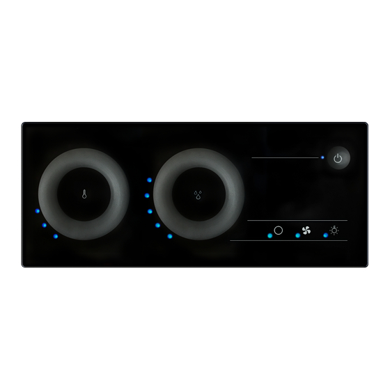
Page 33: Operating Elements
Instructions for use for the user p. 33/50 9. Operating elements 9.1. On the power unit A ON/OFF switch B Light switch 9.2. On the operating unit 1 Power LED 8 Additional devices symbol 2 ON/OFF button 9 Additional devices LED 3 Power level display a Humidity symbol 4 Light symbol... -
Page 34: Touch Wheels
Instructions for use for the user p. 34/50 9.3. Touch wheels The touch wheels b and e can be used to set preset values for the sauna room temperature and for humidity. ● If you wish to increase the preset value, swipe your inger clockwise over the touch wheel. -
Page 35: Touch Wheel Scaling
Instructions for use for the user p. 35/50 9.4. Touch wheel scaling Sauna mode Temperature Number of The preset temperature can be set to be- LEDs lit °C tween 55 °C and 110 °C in sauna mode. The preset or actual temperatures are in- dicated by the number of LEDs which light up on the LED wheel f. -
Page 36: Power Level Display
Instructions for use for the user p. 36/50 The preset humidity can be set to between Humidity Number of 25% and 80%. LEDs lit The preset or actual humidity is indicated by the number of LEDs which light up on the humidity LED wheel c. -
Page 37: Operation
Instructions for use for the user p. 37/50 10. Operation 10.1. Switching on the light on the power unit (cleaning lights) The light in the sauna room can be switched on and off at the power unit inde- pendently of the ON/OFF switch A. ●... -
Page 38: Starting Sauna Mode
Instructions for use for the user p. 38/50 10.4. Starting sauna mode 1. Press the temperature symbol d in the middle of the temperature touch wheel e. ► The sauna heater switches on. 2. Use the temperature touch wheel e to set the preferred temperature. ►... -
Page 39: Switching Off Combi Mode
Instructions for use for the user p. 39/50 3. Press the humidity symbol a in the middle of the humidity touch wheel b. ► The evaporator switches on. 4. Use the humidity touch wheel b to set the preferred humidity. ►... -
Page 40: Switching Off The Additional Device
Instructions for use for the user p. 40/50 When the dimmer switch function is activated When the dimmer switch function for the additional output is activated, the power for the additional device can be set to any level between level 1 to level 7. 1. -
Page 41: Switching On The Light
Instructions for use for the user p. 41/50 10.10. Switching on the light When the dimmer function is activated When the dimmer function for the light is activated, the power for the light can be set to any level between level 1 to level 8. 1. -
Page 42: Switching On The Fan
Instructions for use for the user p. 42/50 10.12. Switching on the fan When the dimmer switch function is activated When the dimmer switch function for the fan is activated, the power for the fan can be set to any level between level 1 to level 8. 1. -
Page 43: Switching Off The Fan
Instructions for use for the user p. 43/50 10.13. Switching off the fan ● Press the fan symbol 6. ► The fan switches off. ► The fan LED 7 goes out. 10.14. Deactivating the operating unit ● Press the ON/OFF button 2 for one second. ►... -
Page 44: Cleaning And Maintenance
Instructions for use for the user p. 44/50 11. Cleaning and maintenance 11.1. Cleaning ATTEnTIOn! Damage to the unit The sauna control unit is protected against jets of water, however direct contact with water could still damage the unit. ● Never immerse the device in water. ●... -
Page 45: Disposal
Instructions for use for the user p. 45/50 12. Disposal ● Please dispose of packaging materials in accordance with the applicable disposal regulations. ● Used devices contain reusable materials and hazardous substances. Therefore, do not dispose of your used device with household waste, but do so in accordance with the locally applicable regulations. -
Page 46: Troubleshooting
Instructions for installation and use p. 46/50 13. Troubleshooting 13.1. Error messages The sauna control unit is equipped with diagnostic software which monitors system statuses at start-up and during operation. As soon as the diagnostic software identiies an error, the sauna control unit switches the sauna heater off. Errors are indicated by a recurring warning tone emitted by the power unit and by the lashing lights on the LED wheels c and f. -
Page 47: Low-Water Display
Instructions for installation and use p. 47/50 13.2. Low-water display The sauna control unit features an automatic low-water shut-off feature which is active in combi mode, as long as your combi heater supports it. If the water tank in the evaporator is empty, this is indicated by a recurring warn- ing tone emitted by the power unit and by the l ashing lights in the humidity LED wheel c. -
Page 48: Technical Data
Instructions for installation and use p. 48/50 14. Technical data Ambient conditions Storage temperature: -25 °C to +70 °C Ambient temperature: -10 °C to +40 °C Relative humidity: max. 95% Dimensions Installation cut-out: 213 x 82 mm Power unit: 307 x 175 x 52 mm Operating unit (with installation frame): 222 x 94 x 38 mm Operating unit (without installation frame):... - Page 49 Instructions for installation and use p. 49/50 Contact rating: 100 W Fuse: 1A T Setting ranges Temperature (sauna mode): 55 °C to 110 °C Temperature (combi mode): 20 °C to 75 °C Humidity: 25 % to 80 % The maximum humidity level which can be set depends on the temperature of the sauna.
- Page 50 GmbH world of wellness Oberregauer Straße 48 4844 Regau, Austria T +43 (0) 7672/277 20-800 F +43 (0) 7672/277 20-801 E info@sentiotec.com www.sentiotec.com...
Need help?
Do you have a question about the just sauna combi and is the answer not in the manual?
Questions and answers