HWH 625 Series Operator's Manual
Computer-controlled leveling system and spacemaker room extension systems
Hide thumbs
Also See for 625 Series:
- Operator's manual (41 pages) ,
- Checklist (3 pages) ,
- Operator's manual (20 pages)
Table of Contents
Advertisement
Quick Links
OPERATOR'S MANUAL
HWH COMPUTER-CONTROLLED
625 SERIES LEVELING SYSTEM
SPACEMAKER ROOM EXTENSION SYSTEMS
Ph: 800/321-3494 (or) 563/724-3396 | Fax: 563/724-3408
AP37456
H H
W
CORPORATION
R
AND
R
FEATURING:
Touch Panel Leveling Control
BI-AXIS Hydraulic Leveling
R
Straight-Acting Jacks
(With Dump)
Cap Extension
Engine Door Lift
HWH COMPUTERIZED LEVELING
R
EXCESS
SLOPE
AUTO
LEVEL
NOT IN
PARK/
BRAKE
AUTO
MANUAL
STORE
DUMP
TRAVEL
EMERGENCY
MODE
STOP
CAUTION!
UNDERSTAND OPERATOR'S MANUAL BEFORE USING. BLOCK FRAME AND TIRES
SECURELY BEFORE REMOVING TIRES OR CRAWLING UNDER VEHICLE.
HWH CORPORATION
(On I-80, Exit 267 South)
2096 Moscow Road | Moscow, Iowa 52760
www.hwh.com
R
EXTEND
EXTEND
MANUAL
RETRACT
RETRACT
ML38929/MP05.6032
10AUG06
Advertisement
Table of Contents

Related Manuals for HWH 625 Series


Summary of Contents for HWH 625 Series
- Page 1 CORPORATION OPERATOR’S MANUAL HWH COMPUTER-CONTROLLED 625 SERIES LEVELING SYSTEM SPACEMAKER ROOM EXTENSION SYSTEMS FEATURING: Touch Panel Leveling Control BI-AXIS Hydraulic Leveling Straight-Acting Jacks (With Dump) Cap Extension Engine Door Lift HWH COMPUTERIZED LEVELING EXCESS SLOPE EXTEND EXTEND AUTO LEVEL NOT IN...
-
Page 2: How To Obtain Warranty Service
HWH CORPORATION personnel will contact you to the problem quickly. If the dealer has difficulty solving determine whether or not your claim is valid. If it is, HWH the problem, he should immediately contact the Customer CORPORATION will authorize repair or replacement of the Service Department, at HWH CORPORATION. -
Page 3: Control Functions
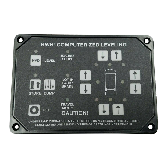
CONTROL IDENTIFICATION 625 SERIES LEVELING SYSTEM COMPUTER-CONTROL "MANUAL DUMP" "EXCESS SLOPE" LOWER FRONT Button Indicator light AUTO LEVEL Manual button Indicator light RAISE FRONT Manual button "AUTO LEVEL" Button HWH COMPUTERIZED LEVELING JACK DOWN "NOT IN PARK" Indicator light EXCESS... -
Page 4: Control Identification
CONTROL IDENTIFICATION FRONT CAP OPERATOR’S PANEL CORPORATION HYDRAULIC ROOM EXTENSION FRONT CAP EXTEND KEY SWITCH CONTROL SWITCH CAUTION! UNDERSTAND OPERATOR’S MANUAL BEFORE USING. KEEP PEOPLE AND OBSTRUCTIONS RETRACT CLEAR OF ROOM WHEN OPERATING. CONTROL FUNCTIONS KEY SWITCH: The KEY SWITCH controls power to the FRONT CAP SWITCH. -
Page 5: Cold Weather Operations
For cold weather information see "COLD WEATHER OPERATIONS" below. The HWH systems with a computer processor monitor the pump run time and will turn the pump off if the run time exceeds a specified time. This time can vary with different systems. Due to available electronics or system design, the pump run time programs will also vary. -
Page 6: Operating Procedures
OPERATING PROCEDURES GENERAL INSTRUCTIONS Maintain adequate clearance in all directions for vehicle, room If the hand / auto brake is not set when the "AUTO LEVEL" extensions, awnings, doors, steps, etc. Vehicle may move in button is pressed, the "NOT IN PARK/BRAKE" light will any direction due to jacks extending or retracting, settling of come on. - Page 7 IMPORTANT: During the Automatic Leveling procedures, support the vehicle. pushing the "AUTO LEVEL", "AUTO STORE" or the "EMERGENCY STOP" button on the HWH touch panel CAUTION: PRIOR TO PUSHING THE "AUTO LEVEL" will stop the automatic leveling function.
- Page 8 "EMERGENCY STOP", "AUTO LEVEL" or the "AUTO The store indicator light will flash and the jacks down STORE" button on the HWH touch panel or engaging buzzer will sound as the vehicle suspension returns to ride the remote AUTO LEVEL/STORE toggle switch during height and the jacks retract.
- Page 9 OPERATING PROCEDURES MANUAL HYDRAULIC OPERATION 1. Place transmission in the recommended position for parking Jacks will extend (or retract) in pairs to raise (or lower) a side the vehicle, and set the parking brake. Turn the ignition to the or end of the vehicle. Any jack not used for leveling can be "ACCESSORY"...
- Page 10 Use the manual valve release for retracting the jacks only removed to gain access. Open valve 1-1/2 to 2 full turns. if the STORE feature on the HWH control panel will not DO NOT turn the 1/4" valve release nut more than retract the jacks.
- Page 11 CAP control switch immediately. DO NOT force the CAP. DO NOT reverse direction of the CAP, contact NOTE: Make sure there is adequate clearance to fully HWH Customer Service for assistance 1-800-321-3494. extend the FRONT CAP NOTE: Releasing the FRONT CAP CONTROL SWITCH 2.
- Page 12 3. Turn the FRONT CAP CONTROL PANEL CAP. DO NOT reverse direction of the CAP, contact KEY SWITCH to "ON". HWH Customer Service for assistance 1-800-321-3494. 4. To retract the FRONT CAP press and hold the NOTE: Releasing the FRONT CAP CONTROL SWITCH FRONT CAP CONTROL SWITCH in the "RETRACT"...
- Page 13 TOGGLE SWITCH immediately. DO NOT force the LIFT. DO NOT reverse direction of the LIFT, contact 1. The park brake must be set to operate the HWH Customer Service for assistance 1-800-321-3494. ENGINE DOOR LIFT. NOTE: Releasing the LIFT CONTROL TOGGLE 2.
- Page 14 TOGGLE SWITCH immediately. ENGINE DOOR LIFT. DO NOT force the DOOR LIFT. DO NOT reverse direction of the LIFT, contact HWH Customer Service 2. Lift the mechanical door stops into their stored position for assistance 1-800-321-3494. and insert the retaining pins.
-
Page 15: Maintenance
Dexron automatic transmission fluid contains red dye and can cause staining should a leak occur. DO NOT USE All four jacks, any HWH room extensions and any other HWH brake fluid or hydraulic jack fluid. Use of these can damage hydraulic mechanisms should be completely retracted before seals. - Page 16 Move the adjustment for that light very, very, slightly in qualified RV repair center, your vehicle or coach the OPPOSITE direction that is given in the above manufacturer, or HWH CORPORATION for service or repair. instructions for LED’s A, B, C, and D. This will allow MP45.3259 07MAY09 MP44.1501...
- Page 17 BREATHER CAP - DIPSTICK - 1/4" NUT DRIVER 1 1/2" DIAMETER VALVE RELEASE SOLENOID VALVE NOTE: DO NOT turn the valve release nut more than 4 and 1/2 (four and one half) turns counter clockwise. Damage to the valve may result. VALVE RELEASE PLASTIC PLUG 2 1/4"...
Need help?
Do you have a question about the 625 Series and is the answer not in the manual?
Questions and answers