HWH 625 Series Operator's Manual
Computer-controlled leveling system
Hide thumbs
Also See for 625 Series:
- Operator's manual (41 pages) ,
- Checklist (3 pages) ,
- Operator's manual (17 pages)
Table of Contents
Advertisement
Quick Links
OPERATOR'S MANUAL
HWH COMPUTER-CONTROLLED
625 SERIES LEVELING SYSTEM
Ph: 800/321-3494 (or) 563/724-3396 | Fax: 563/724-3408
AP38141
H H
W
CORPORATION
R
FOR FIFTH WHEEL RVS
FEATURING:
Touch Panel Leveling Control
BI-AXIS Hydraulic Leveling
R
Straight-Acting Jacks
Front Jack Equalization
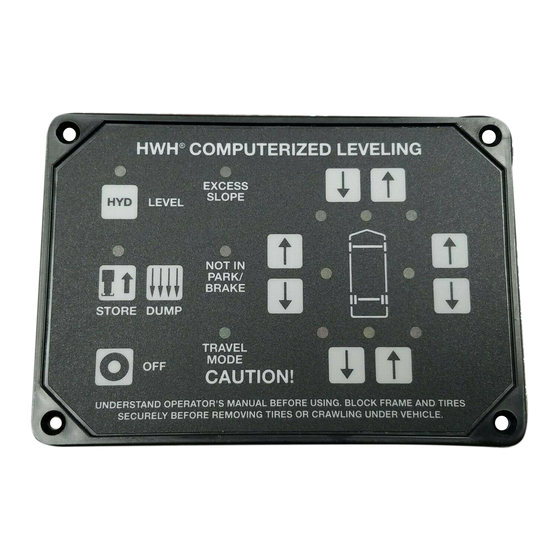
HWH COMPUTERIZED LEVELING
EXCESS
ON
SLOPE
AUTO
NOT IN
PARK/
STORE
BRAKE
TRAVEL
MODE
OFF
CAUTION!
UNDERSTAND OPERATOR'S MANUAL BEFORE USING. BLOCK FRAME AND TIRES
SECURELY BEFORE REMOVING TIRES OR CRAWLING UNDER VEHICLE.
HWH CORPORATION
(On I-80, Exit 267 South)
2096 Moscow Road | Moscow, Iowa 52760
www.hwh.com
R
ML38142/MP04.2528
10SEP09
Advertisement
Table of Contents

Related Manuals for HWH 625 Series


Summary of Contents for HWH 625 Series
- Page 1 CORPORATION OPERATOR’S MANUAL HWH COMPUTER-CONTROLLED 625 SERIES LEVELING SYSTEM FOR FIFTH WHEEL RVS FEATURING: Touch Panel Leveling Control BI-AXIS Hydraulic Leveling Straight-Acting Jacks Front Jack Equalization HWH COMPUTERIZED LEVELING EXCESS SLOPE AUTO NOT IN PARK/ STORE BRAKE TRAVEL MODE CAUTION! UNDERSTAND OPERATOR’S MANUAL BEFORE USING.
-
Page 2: How To Obtain Warranty Service
HWH CORPORATION personnel will contact you to the problem quickly. If the dealer has difficulty solving determine whether or not your claim is valid. If it is, HWH the problem, he should immediately contact the Customer CORPORATION will authorize repair or replacement of the Service Department, at HWH CORPORATION. -
Page 3: Control Identification
This switch controls power lights. They are functional only when the system is on, to the HWH control system. This is an optional switch from and the jacks are extended 1/4 to 1/2 inch. HWH. The system should have a master power switch. -
Page 4: Cold Weather Operations
For cold weather information see "COLD WEATHER OPERATIONS" below. The HWH systems with a computer processor monitor the pump run time and will turn the pump off if the run time exceeds a specified time. This time can vary with different systems. Due to available electronics or system design, the pump run time programs will also vary. -
Page 5: Operating Procedures
OPERATING PROCEDURES GENERAL INSTRUCTIONS Maintain adequate clearance in all directions for vehicle, room Any time a hydraulic leveling process is interrupted, retract extensions, awnings, doors, steps, etc. Vehicle may move in the jacks according to the JACK RETRACTION Section and any direction due to jacks extending or retracting, settling of then restart the leveling process. - Page 6 1. Trailer must be unhitched from the tow vehicle before level- 6. The jack stop rods should be adjusted immediately after ing. The HWH front jacks may be used to lift the trailer for the leveling and stabilizing procedure is finished.
- Page 7 OPERATING PROCEDURES 625 SERIES LEVELING SYSTEM JACK RETRACTION CAUTION: THE OPERATOR MUST BE SURE THAT IMPORTANT: DO NOT interrupt power to the leveling THERE ARE NO OBJECTS UNDER THE VEHICLE AND THAT system while the "STORE" indicator light is blinking.
-
Page 8: Manual Leveling
1. Trailer must be unhitched from the tow vehicle before level- 7. The jack stop rods should be adjusted immediately after ing. The HWH front jacks may be used to lift the trailer for the leveling and stabilizing procedure is finished. - Page 9 Replace the protective plastic plug. Use the manual valve release for retracting the jacks only if the STORE feature on the HWH control panel will not 4. Retract the rear jacks by opening the correct valves. retract the jacks.
- Page 10 All major components of the system can be replaced become caked or clogged with mud. This condition may with rebuilt units or can be sent to HWH CORPORATION to hamper the proper operation of the leveling system. This be rebuilt, when the system is out of warranty.
- Page 11 SENSING UNIT MAINTENANCE/SERVICE SENSING UNIT ACCURACY TOLERANCE The sensing unit has an accuracy tolerance of ± 5.4 inches front to rear and ± 1 inch side to side on a 36 foot vehicle. Typical leveling results will be better. SENSING UNIT ADJUSTMENT Level the vehicle by placing a bubble level in the center of NOTE: If opposing LED’s are lit, there is a problem with the freezer floor or upon whichever surface within the vehicle...
- Page 12 HYDRAULIC CONNECTION DIAGRAM 310 SERIES LEVELING SYSTEM WITH FRONT JACK EQUALIZATION FIFTH WHEEL NOTE: VIEW IS SHOWN WITH LEVELING MANIFOLD ONLY, OTHER MANIFOLDS EMERGENCY MAY BE ATTACHED. VALVE RELEASE PUMP/MANIFOLD ASSEMBLY NOTE: BEFORE OPERATING EMERGENCY VALVE RELEASE, READ AND UNDERSTAND PROCEDURE FOR EMERGENCY RETRACT IN OPERATOR’S INSTRUCTIONS.
- Page 13 HYDRAULIC SCHEMATIC 310 SERIES LEVELING SYSTEM WITH FOUR STRAIGHT-ACTING JACKS RELIEF VALVE 12 VOLT D.C. HYDRAULIC SOLENOID MANIFOLD POWER UNIT ASSEMBLY RETURN PRESSURE PRESSURE/RETURN 50 PSI SHUTTLE VALVE SWITCH CHECK SOL.VALVE SOL.VALVE SOL.VALVE SOL.VALVE SOL.VALVE VALVE EQUALIZE INNER CHECK VALVE OUTER LEFT RIGHT...
- Page 14 ELECTRICAL CONNECTION DIAGRAM 625 SERIES LEVELING SYSTEM FIFTH WHEEL TRAILERS TOUCH PANEL - JACK WARNING LIGHTS AND PRESSURE SWITCHES PRESSURE PRESSURE SWITCH SWITCH WARNING WARNING SWITCH SWITCH 6235 2000 1000 6235 1200 2200 TOUCH PANEL HWH COMPUTERIZED LEVELING EXCESS SLOPE...
-
Page 15: Electrical Connection Diagram
ELECTRICAL CONNECTION DIAGRAM 625 OR 625S SERIES LEVELING SYSTEMS TOUCH PANEL CONNECTIONS HWH COMPUTERIZED LEVELING EXCESS SLOPE AUTO NOT IN PARK/ STORE BRAKE TRAVEL MODE CAUTION! UNDERSTAND OPERATOR’S MANUAL BEFORE USING. BLOCK FRAME AND TIRES SECURELY BEFORE REMOVING TIRES OR CRAWLING UNDER VEHICLE. - Page 16 ELECTRICAL CONNECTION DIAGRAM 625 SERIES LEVELING SYSTEM - FIFTH WHEEL TRAILERS CONTROL BOX CONNECTION INFORMATION 12 PIN BROWN PIN 1 PIN 12 12 PIN PIN 1 BLACK PIN 1 PIN 12 12 PIN 8 PIN PIN 1 GRAY BLACK PIN 4...
- Page 17 ELECTRICAL CONNECTION DIAGRAM 625 SERIES LEVELING SYSTEM - FIFTH WHEEL TRAILERS CONTROL BOX - LED - FUSE LOCATION AND DESCRIPTION RELAY DESCRIPTION FUSE 1-YELLOW RIGHT REAR COIL 2-RED RIGHT REAR OUTPUT F1 - 15 AMP 3-YELLOW LEFT REAR COIL 4-RED...
- Page 18 ELECTRICAL CONNECTION DIAGRAM 625 SERIES LEVELING SYSTEM - FIFTH WHEEL TRAILERS LEVELING MANIFOLD PUMP AND MASTER RELAYS SHUTTLE VALVE VIEW A-A 3400 RIGHT REAR RR VALVE 6240 SOLENOID VALVE 4400 LEFT REAR LR VALVE 6241 SOLENOID VALVE 1400 LEFT FRONT...
- Page 19 INFORMATION/INSTRUCTION SHEET HYDRAULIC SOLENOID VALVE INDENTIFICATION - MANUAL OPERATIONS - REPLACEMENT REPLACEMENT VALVES WILL HAVE A VALVE RELEASE CAM SOLENOID VALVES WITH CAM RELEASE BREATHER CAP W/NUT DRIVER 1 1/2" DIAMETER SOLENOID VALVE CAM RELEASE VALVE CLOSED Default position THE BREATHER CAP IS NOTE: The cam release may be LOCATED ON THE TOP rotated in any direction on the...
Need help?
Do you have a question about the 625 Series and is the answer not in the manual?
Questions and answers