HWH 625 Series Operator's Manual
Computer-controlled leveling system and spacemaker room extension systems for trailers
Hide thumbs
Also See for 625 Series:
- Operator's manual (41 pages) ,
- Checklist (3 pages) ,
- Operator's manual (10 pages)
Table of Contents
Advertisement
Quick Links
OPERATOR'S MANUAL
HWH COMPUTER-CONTROLLED
625 SERIES LEVELING SYSTEM
SPACEMAKER ROOM EXTENSION SYSTEMS
Ph: 800/321-3494 (or) 563/724-3396 | Fax: 563/724-3408
AP40391
H H
W
CORPORATION
R
AND
R
FOR TRAILERS
FEATURING:
Touch Panel Leveling Control
BI-AXIS Hydraulic Leveling
R
Straight-Acting Jacks
Multiple Room Extensions
No Jack Stop Rods
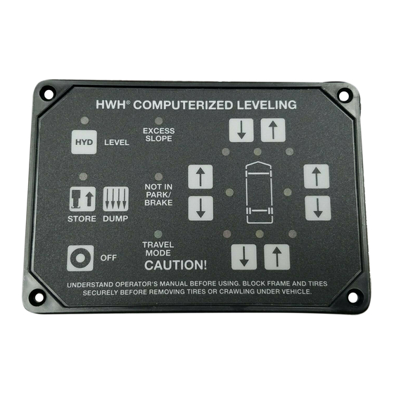
HWH COMPUTERIZED LEVELING
R
EXCESS
SLOPE
AUTO
LEVEL
NOT IN
PARK/
BRAKE
AUTO
STORE
TRAVEL
EMERGENCY
MODE
STOP
CAUTION!
UNDERSTAND OPERATOR'S MANUAL BEFORE USING. BLOCK FRAME AND TIRES
SECURELY BEFORE REMOVING TIRES OR CRAWLING UNDER VEHICLE.
HWH CORPORATION
(On I-80, Exit 267 South)
2096 Moscow Road | Moscow, Iowa 52760
www.hwh.com
R
EXTEND
EXTEND
MANUAL
RETRACT
RETRACT
ML40392/MP04.2801
08MAR07
Advertisement
Table of Contents

Related Manuals for HWH 625 Series


Summary of Contents for HWH 625 Series
- Page 1 CORPORATION OPERATOR’S MANUAL HWH COMPUTER-CONTROLLED 625 SERIES LEVELING SYSTEM SPACEMAKER ROOM EXTENSION SYSTEMS FOR TRAILERS FEATURING: Touch Panel Leveling Control BI-AXIS Hydraulic Leveling Straight-Acting Jacks Multiple Room Extensions No Jack Stop Rods HWH COMPUTERIZED LEVELING EXCESS SLOPE EXTEND EXTEND AUTO...
-
Page 2: How To Obtain Warranty Service
HWH CORPORATION personnel will contact you to the problem quickly. If the dealer has difficulty solving determine whether or not your claim is valid. If it is, HWH the problem, he should immediately contact the Customer CORPORATION will authorize repair or replacement of the Service Department, at HWH CORPORATION. -
Page 3: Computer Control
625S / 725 / 2000 SERIES LEVELING SYSTEM COMPUTER-CONTROL "EXCESS SLOPE" Indicator light LOWER FRONT Manual button "NOT IN PARK" Indicator light RAISE FRONT Manual button HWH COMPUTERIZED LEVELING JACK DOWN AUTO LEVEL Indicator light Indicator light (4) red EXCESS SLOPE "AUTO LEVEL"... -
Page 4: Control Identification
CONTROL IDENTIFICATION ROOM OPERATOR’S PANEL CORPORATION HYDRAULIC ROOM EXTENSION EXTEND ROOM CONTROL KEY SWITCH SWITCH CAUTION! UNDERSTAND OPERATOR’S MANUAL BEFORE USING. KEEP PEOPLE AND OBSTRUCTIONS RETRACT CLEAR OF ROOM WHEN OPERATING. CONTROL FUNCTIONS KEY SWITCH: The KEY SWITCH controls power to the ROOM ROOM CONTROL SWITCH: The ROOM CONTROL SWITCH CONTROL SWITCH. -
Page 5: Cold Weather Operations
For cold weather information see "COLD WEATHER OPERATIONS" below. The HWH systems with a computer processor monitor the pump run time and will turn the pump off if the run time exceeds a specified time. This time can vary with different systems. Due to available electronics or system design, the pump run time programs will also vary. -
Page 6: Operating Procedures
OPERATING PROCEDURES GENERAL INSTRUCTIONS Maintain adequate clearance in all directions for vehicle, room Any time a hydraulic leveling process is interrupted, retract extensions, awnings, doors, steps, etc. Vehicle may move in the jacks according to the JACK RETRACTION Section and any direction due to jacks extending or retracting, settling of then restart the leveling process. - Page 7 1. Trailer must be unhitched from the tow vehicle before level- NOTE: The front yellow LEVEL light must be on before ing. The HWH front jacks may be used to lift the trailer for automatic leveling will function. unhitching. If auxiliary jacks are used to unhitch the trailer, extend the HWH front jacks to the ground and retract the 3.
- Page 8 OPERATING PROCEDURES PREPARATION FOR TRAVEL CAUTION: CAUTION: THE OPERATOR MUST BE SURE THAT ONLY USE THE "AUTO STORE" THERE ARE NO OBJECTS UNDER THE VEHICLE AND THAT BUTTON IF THE TRAILER IS HITCHED TO A TOW ALL PEOPLE ARE CLEAR OF THE VEHICLE. VEHICLE OR SECURELY SUPPORTED BY THE EXISTING LANDING GEAR.
-
Page 9: Manual Leveling
1. Trailer must be unhitched from the tow vehicle before level- 3. A lit yellow LEVEL light indicates that the side, end or corner ing. The HWH front jacks may be used to lift the trailer for of the trailer is low. Pushing the up arrow for corresponding yellow unhitching. - Page 10 Replace the protective plastic plug. Use the manual valve release for retracting the jacks only if the STORE feature on the HWH control panel will not 4. Retract the front jacks by opening the correct valves. retract the jacks.
- Page 11 Replace the protective plastic plug. Use the manual valve release for retracting the jacks only if the STORE feature on the HWH control panel will not 4. Retract the rear jacks by opening the correct valves. retract the jacks.
- Page 12 2. Unlock all room-locking devices to include travel IMPORTANT: Do not hold the ROOM CONTROL SWITCH clamps/locks supplied by manufacturers other than HWH. in the "EXTEND" position for more than ten seconds after the room is fully extended (and down if applicable) or stops moving.
- Page 13 DO NOT reverse direction of the room, contact 1. The park brake must be set, if applicable. HWH Customer Service for assistance 1-800-321-3494. The room will not operate if the park brake is not set. NOTE: Releasing the ROOM CONTROL SWITCH will 2.
- Page 14 A MANUAL RETRACT WINCH PROVIDED place the RATCHET LEVER in its ON position and slowly BY HWH IS EQUIPPED FOR MANUALLY RETRACTING THE rotate the WINCH HANDLE clockwise until the ROOM ONLY. IT IS NOT TO BE USED FOR LIFTING OR ANY RATCHET LEVER locks.
-
Page 15: Maintenance
Dexron automatic transmission fluid contains red dye and can cause staining should a leak occur. DO NOT USE All jacks and any HWH room extension cylinders should be brake fluid or hydraulic jack fluid. Use of these can damage completely retracted before checking the oil level. The oil seals. - Page 16 CANNOT ROLL FORWARD OR BACKWARD. qualified RV repair center, your vehicle or coach manufacturer, or HWH CORPORATION for service or repair. Set the park/brake. Switch the ignition to the "ACC" or "ON" position. Push the "ON" switch. Release the parking brake.
- Page 17 SENSING UNIT MAINTENANCE/SERVICE SENSING UNIT ACCURACY TOLERANCE The sensing unit has an accuracy tolerance of ± 5.4 inches front to rear and ± 1 inch side to side on a 36 foot vehicle. Typical leveling results will be better. SENSING UNIT ADJUSTMENT Level the vehicle by placing a bubble level in the center of NOTE: If opposing LED’s are lit, there is a problem with the freezer floor or upon whichever surface within the vehicle...
- Page 18 INFORMATION/INSTRUCTION SHEET HYDRAULIC SOLENOID VALVE INDENTIFICATION - MANUAL OPERATIONS - REPLACEMENT REPLACEMENT VALVES WILL HAVE A VALVE RELEASE CAM SOLENOID VALVES WITH CAM RELEASE BREATHER CAP W/NUT DRIVER 1 1/2" DIAMETER SOLENOID VALVE CAM RELEASE VALVE CLOSED Default position THE BREATHER CAP IS NOTE: The cam release may be LOCATED ON THE TOP rotated in any direction on the...
Need help?
Do you have a question about the 625 Series and is the answer not in the manual?
Questions and answers