HWH 625 Series Operator's Manual
Touch panel-controlled leveling system
Hide thumbs
Also See for 625 Series:
- Operator's manual (41 pages) ,
- Checklist (3 pages) ,
- Operator's manual (10 pages)
Advertisement
Quick Links
Download this manual
See also:
Operator's Manual
OPERATOR'S MANUAL
HWH TOUCH PANEL-CONTROLLED
625 SERIES LEVELING SYSTEM
UNDERSTAND OPERATOR'S MANUAL BEFORE USING. BLOCK FRAME AND TIRES
Ph: 800/321-3494 (or) 563/724-3396 | Fax: 563/724-3408
AP28848
H H
W
CORPORATION
R
FEATURING:
Touch Panel Leveling Control
BI-AXIS Hydraulic Leveling
R
Straight-Acting Jacks
(Optional Manual Pilot Dump)
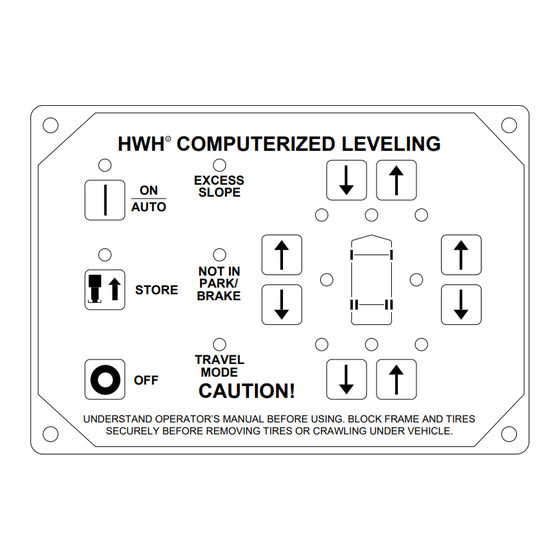
HWH COMPUTERIZED LEVELING
R
EXCESS
ON
SLOPE
AUTO
NOT IN
PARK/
STORE
BRAKE
TRAVEL
MODE
OFF
CAUTION!
SECURELY BEFORE REMOVING TIRES OR CRAWLING UNDER VEHICLE.
HWH CORPORATION
(On I-80, Exit 267 South)
2096 Moscow Road | Moscow, Iowa 52760
www.hwh.com
R
ML29619/MP05.6002
17DEC02
Advertisement

Subscribe to Our Youtube Channel
Related Manuals for HWH 625 Series


Summary of Contents for HWH 625 Series
- Page 1 CORPORATION OPERATOR’S MANUAL HWH TOUCH PANEL-CONTROLLED 625 SERIES LEVELING SYSTEM FEATURING: Touch Panel Leveling Control BI-AXIS Hydraulic Leveling Straight-Acting Jacks (Optional Manual Pilot Dump) HWH COMPUTERIZED LEVELING EXCESS SLOPE AUTO NOT IN PARK/ STORE BRAKE TRAVEL MODE CAUTION! UNDERSTAND OPERATOR’S MANUAL BEFORE USING. BLOCK FRAME AND TIRES SECURELY BEFORE REMOVING TIRES OR CRAWLING UNDER VEHICLE.
- Page 2 HWH CORPORATION personnel will contact you to the problem quickly. If the dealer has difficulty solving determine whether or not your claim is valid. If it is, HWH the problem, he should immediately contact the Customer CORPORATION will authorize repair or replacement of the Service Department, at HWH CORPORATION.
-
Page 3: White-
CONTROL IDENTIFICATION 625 SERIES LEVELING SYSTEM COMPUTER-CONTROL LOWER FRONT HYDRAULIC "EXCESS SLOPE" OPERATION Manual button Indicator light Indicator light RAISE FRONT Manual button ON/AUTO Button JACK DOWN HWH COMPUTERIZED LEVELING "NOT IN PARK" Indicator light EXCESS Indicator light SLOPE (4) red (R) - Page 4 OPERATING PROCEDURES GENERAL INSTRUCTIONS Maintain adequate clearance in all directions for vehicle, room If the hand / auto brake is not set when the ""I"" button extensions, awnings, doors, steps, etc. Vehicle may move in is pressed, the "NOT IN PARK/BRAKE" light will come on. any direction due to jacks extending or retracting, settling of When the ""I""...
- Page 5 OPERATING PROCEDURES 625 SERIES LEVELING SYSTEM AUTOMATIC HYDRAULIC LEVELING 1. Place transmission in the recommended position for EXCESS SLOPE SITUATION: In the event the jacks are parking vehicle and set parking brake. Turn the coach unable to level the coach, the "EXCESS SLOPE" light will engine off.
- Page 6 Use the manual valve release for retracting the jacks only removed to gain access. Open valve 1-1/2 to 2 full turns. if the STORE feature on the HWH control panel will not DO NOT turn the 1/4" valve release nut more than retract the jacks.
- Page 7 All major components of the system can be replaced with ice. This may cause the leveling system to function with rebuilt parts or can be sent to HWH CORPORATION to improperly. To eliminate this problem, periodically check the be rebuilt, when the system is out of warranty.
- Page 8 SENSING UNIT MAINTENANCE/SERVICE SENSING UNIT ACCURACY TOLERANCE The sensing unit has an accuracy tolerance of ± 5.4 inches front to rear and ± 1 inch side to side on a 36 foot vehicle. Typical leveling results will be better. SENSING UNIT ADJUSTMENT To adjust the sensing unit, first the vehicle must be level.
- Page 9 HYDRAULIC LINE CONNECTION DIAGRAM 625 OR 625S SERIES LEVELING SYSTEMS (WITH 4 STRAIGHT-ACTING JACKS) NOTE: BEFORE OPERATING ANY MANUAL VALVE RELEASE READ AND UNDERSTAND PROCEDURE FOR MANUAL JACK RETRACTION IN OPERATOR’S INSTRUCTIONS. THIS MANIFOLD IS SHOWN WITH (1) LARGE VALVE WITH A VALVE RELEASE "T"-HANDLE, (2) SMALL VALVES WITH VALVE RELEASE NUTS AND (1) LARGE VALVE WITH A VALVE RELEASE NUT.
- Page 10 HYDRAULIC SCHEMATIC DIAGRAM 625 - 625S - 725 SERIES LEVELING SYSTEM SHUTTLE VALVE 50 PSI SWITCH MAY NOT 800 PSI TO LEVELING SYSTEM STEEL TUBE SHIFT SHUTTLE BE ON ALL SOLENOID MANIFOLD ASSEMBLY 625 MANIFOLDS VALVE 3000 PSI SWITCH JACK SOLENOID VALVES (4) 50 PSI SWITCH...
-
Page 11: Black
ELECTRICAL CONNECTION DIAGRAM 625 SERIES LEVELING SYSTEM PARK BRAKE - MASTER WARNING LIGHT AND BUZZER TOUCH PANEL - JACK WARNING LIGHTS AND PRESSURE SWITCHES PRESSURE PRESSURE SWITCH SWITCH WARNING WARNING SWITCH SWITCH 6235 2000 1000 6235 1200 2200 CONNECT TO... -
Page 12: Black
TO 50 LB PRESSURE SWITCH - 8101 LEVELING MANIFOLD 3400 7601 2400 7600 1400 6240 4400 6240 TO HWH GROUND STUD - 6240 TO 3000 LB PRESSURE SWITCH - 8100 12 PIN BROWN 4 PIN LEVELING GRAY MANIFOLD 8 PIN BLACK... - Page 13 ELECTRICAL CONNECTION DIAGRAM 625 SERIES LEVELING SYSTEM CONTROL BOX CONNECTION INFORMATION 12 PIN BROWN PIN 1 PIN 12 12 PIN PIN 1 BLACK PIN 1 PIN 12 12 PIN 8 PIN PIN 1 GRAY BLACK PIN 4 PIN 12 4 PIN...
-
Page 14: White-
NOTE: THE TRAVEL RELAY IS NOT USED ON IF THE YELLOW LED’S ARE WORKING BUT NO RED LED VEHICLES EQUIPPED WITH HWH AIR DUMP SYSTEMS. IS COMING ON THERE MAY BE PROBLEM WITH INPUT IT IS ONLY USED WITH PILOT OPERATED AIR DUMP VOLTAGE IN THE 4-PIN CONNECTOR. -
Page 15: White
BREATHER CAP - DIPSTICK - 1/4" NUT DRIVER 1 1/2" DIAMETER VALVE RELEASE SOLENOID VALVE NOTE: DO NOT turn the valve release nut more than 4 and 1/2 (four and one half) turns counter clockwise. Damage to the valve may result. VALVE RELEASE PLASTIC PLUG 2 1/4"...
Need help?
Do you have a question about the 625 Series and is the answer not in the manual?
Questions and answers