Advertisement
Quick Links
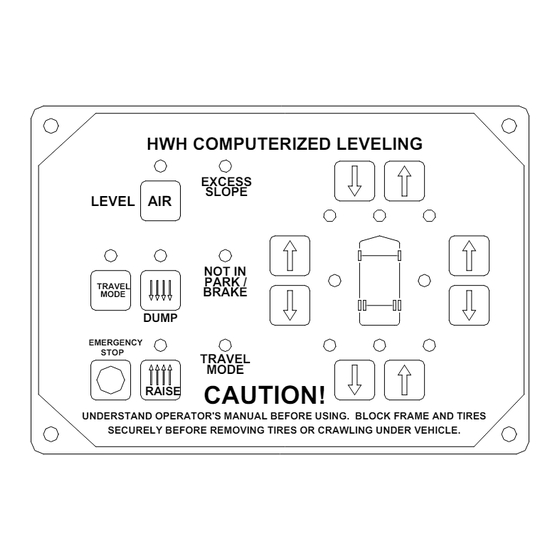
SERVICE MANUAL
HWH COMPUTER-CONTROLLED
R
700 SERIES AIR LEVELING SYSTEM
2096 Moscow Road | Moscow, Iowa 52760
Ph: 800/321-3494 (or) 563/724-3396 | Fax: 563/724-3408
FEATURING:
R
HWH COMPUTERIZED LEVELING
EXCESS
SLOPE
LEVEL AIR
NOT IN
PARK /
TRAVEL
BRAKE
MODE
DUMP
EMERGENCY
STOP
TRAVEL
MODE
RAISE
CAUTION!
UNDERSTAND OPERATOR'S MANUAL BEFORE USING. BLOCK FRAME AND TIRES
SECURELY BEFORE REMOVING TIRES OR CRAWLING UNDER VEHICLE.
HWH CORPORATION
(On I-80, Exit 267 South)
www.hwh.com
C:\TEMP\ml59101.doc | Revised: 20JUN18 | Page 1 of 39
R
Advertisement

Related Manuals for HWH 700 Series


Summary of Contents for HWH 700 Series
- Page 1 SERVICE MANUAL HWH COMPUTER-CONTROLLED 700 SERIES AIR LEVELING SYSTEM FEATURING: HWH COMPUTERIZED LEVELING EXCESS SLOPE LEVEL AIR NOT IN PARK / TRAVEL BRAKE MODE DUMP EMERGENCY STOP TRAVEL MODE RAISE CAUTION! UNDERSTAND OPERATOR'S MANUAL BEFORE USING. BLOCK FRAME AND TIRES SECURELY BEFORE REMOVING TIRES OR CRAWLING UNDER VEHICLE.
- Page 2 TROUBLE SHOOTING GUIDE. In many cases this will save time and mistakes when trouble shooting a system. This repair manual is offered as a guide only. It is impossible to anticipate every problem or combination of problems. For any problems encountered that are not addressed in this manual, contact HWH Corporation for assistance. (800-321- 3494) PROCEED WITH TROUBLE SHOOTING GUIDE C:\TEMP\ml59101.doc | Revised: 20JUN18 | Page 2 of 39...
- Page 3 NOTE: HWH CORPORATION ASSUMES NO with knowledge of air suspension and automotive electrical LIABILITY FOR DAMAGES OR INJURIES systems. People with little or no experience with HWH leveling RESULTING FROM THE INSTALLATION OR should contact HWH technical service (800-321-3494) before REPAIR OF THIS PRODUCT.
-
Page 4: Control Identification
CONTROL IDENTIFICATION "EXCESS SLOPE" HARD RESET SWITCH LIGHT (SEE HWH LIGHTED RESET SWITCH) "NOT IN PARK" LIGHT MASTER WARNING LIGHT LEVELING SYSTEM ACTIVE LIGHT LOWER FRONT BUTTON "AIR" (ON) BUTTON RAISE FRONT BUTTON HWH COMPUTERIZED LEVELING DUMP LIGHT WARNING LIGHTS... - Page 5 If you are not familiar with the system, it would be a good idea to review this section. The 700 series air leveling system is a computer controlled BI-AXIS push button system. The system has one touch automatic operation or can be controlled manually.
- Page 6 AUTOMATIC OPERATION It is best to leave the engine running for the automatic leveling procedure. The ignition must be in the “ON” or “ACC” position to initiate automatic leveling. The park brake must be set. If not set, the “NOT IN PARK/BRAKE” light will come on while pushing the “AIR”...
- Page 7 MANUAL OPERATION The UP and DOWN arrow button on the right side of the touch panel allow manual control of the air bags. The ignition must be in the “ON” or “ACC” position and the park brake must be set for the UP and DOWN arrows to function. There are four sets of buttons, front, left side, right side and rear.
-
Page 8: Part 2 - Trouble Shooting
TROUBLE SHOOTING BASICS (Please read before continuing) When trouble shooting the 700 series air leveling system, it is best to run the system in the manual mode to check individual functions before operating the system in the automatic mode. If the system won’t work in manual, it won’t work in automatic. - Page 9 REFER TO MP84.3180 Step 1b. The If a yellow level light is on, replace the touch panel. If a level HWH COMPUTERIZED LEVELING green TRAVEL light is not lit, push the “RAISE” or “DUMP” button. If the light EXCESS...
- Page 10 TROUBLE SHOOTING PROBLEM SOLUTION DIAGRAMS Step 1b. Cont. ALL LINK LIGHTS ARE OFF – Make sure there is a good ground on the MIOM ground stud. Fix if necessary. With the ignition on, check at the main connector of the front MIOM for +12 power between the red 6102 wire (pin D1) and the white 6230 wire (pin D3).
- Page 11 Step 2b. One or If there is a Height Control Valve for each side of the axle, the more air bags issue could be HWH or the Height control valve. are not inflated. The blue Travel WARNING: MAKE SURE THE FRAME OF THE VEHICLE IS...
- Page 12 If +12 is not present, there is an issue with the transmission output, the 9900 wire, its connections to the HWH MIOM or the transmission speed switch. If +12 is present, replace the touch panel. FRONT VIEW OF I/O MODULE...
- Page 13 TROUBLE SHOOTING PROBLEM SOLUTION DIAGRAMS Step 3c. None of Check that all exhaust ports are clear and not plugged with the air bags will dirt or debris. Clean if necessary. Use caution as the air will deflate start to dump after cleaning the ports if the DUMP light is still flashing.
- Page 14 For the sides or rear of the vehicle or if the front manifold does not have a regulator, the issue will be with the vehicle air CHECK VALVES supply or suspension components. All the HWH manifolds PRESSURE REGULATOR can do is let air into the air bags. How high the vehicle raises REFER TO MP74.2670A...
- Page 15 MIOM, the 9700 wire or a problem at REFER TO MP84.3181 the compressor. Note: Some early 700 series compressors were grounded through the compressor mounting bracket. More recent compressors will have a white ground wire with a Packard connector.
- Page 16 TROUBLE SHOOTING PROBLEM SOLUTION DIAGRAMS Step 5a. Cont. If there is no voltage on terminal 3 (red battery wire), WHITE GROUND check the fuse for this wire. On older systems the fuse is 12 VOLT close to the compressor. On later models, the fuse is close to ESSEX RELAY the source connection.
- Page 17 TROUBLE SHOOTING PROBLEM SOLUTION DIAGRAMS Step 6b. Unplug the level sensing unit. If all touch panel level lights Opposing level go out, the issue is the sensing unit or a short in the harness. lights are on or Unplug the main front MIOM connector and make sure no a touch panel sensing unit wires are shorted together.
- Page 18 TROUBLE SHOOTING Step 8. TEST FOR 20 PSI AIR BAG PRESSURE SWITCHES – Turn the ignition key to the “ON” or “ACC” position. Use the “DUMP” button to exhaust all air from the all of the air bags. With the bags deflated, the air bag pressure switch contacts should be closed.
- Page 19 TO +12 BATTERY If +12 is not present, there is an issue with the transmission output, the 9900 wire, its connections to the HWH MIOM or the transmission speed switch. If +12 is present, replace the touch panel.
- Page 20 AUTOMATIC DIAGNOSTICS Step 12. For a detailed explanation of the automatic leveling sequence, see “AUTOMATIC OPERATION” in PART 1 of this manual. Make sure the park brake is set. Start the engine and make sure the air tanks are full. Push the “AIR” button.
- Page 21 TROUBLE SHOOTING PROBLEM SOLUTION DIAGRAMS Step 12d. The The front MIOM has a latch in LED. With the ignition on, that LEVELING LED should be on. SYSTEM ACTIVE light The latch in LED is not on. Turn the ignition off; unplug the LINK LIGHT turns off when front MIOM main connector, the 2-pin high current connector...
-
Page 22: Instruction Sheet
INSTRUCTION SHEET SENSING UNIT MAINTENANCE/SERVICE REMOTE MOUNTED "POTTED" ELECTRONIC SENSING UNIT SENSING UNIT ACCURACY TOLERANCE The sensing unit has an accuracy tolerance of ± 5.4 inches front to rear and ±1 inch side to side on a 36 foot vehicle. Typical leveling results will be better. SENSING UNIT ADJUSTMENT / WITH ADJUSTING ENHANCEMENT Level the vehicle by placing a bubble level in the center of the Move the vehicle to an unlevel position and level the... - Page 23 EXHAUST 4. Push and hold the HWH touch panel front DOWN ARROW button until the front air bags are empty. Check the air bags. Repeat this with the rear DOWN ARROW button. Again, check the air bags.
- Page 24 AIR LINE CONNECTION DIAGRAM 4 - POINT AIR LEVELING SYSTEM SEE AIR LINE CONNECTION DIAGRAM - HWH AIR COMPRESSOR LINES FROM FRONT HEIGHT CONTROL MANIFOLD VALVES TO SUSPENSION LINES TO AIR BAGS SUPPLY AIR BAG HEIGHT CONTROL VALVE (4) SEE FRONT AND REAR AIR SOLENOID MANIFOLD...
- Page 25 AIR LINE CONNECTION DIAGRAM 4-POINT LEVELING SYSTEM SCHEMATIC PRESSURE SWITCHES FRONT AND REAR SEE AIR LINE CONNECTION DIAGRAM - HWH AIR COMPRESSOR SCHEMATIC MANIFOLD ASSEMBLY TRAV. TRAV. LOWER LOWER RAISE RAISE MANIFOLD ASSEMBLY NORMALLY TRAV. TRAV. CLOSED PRESSURE SWITCH 20 PSI...
- Page 26 AIR SOLENOID MANIFOLD 6 VALVE WITH TWO PRESSURE SWITCHES AND BY-PASS VALVES FRONT AIR MANIFOLD REAR VIEW LINE FROM 3.400" HEIGHT CONTROL NOTE: I/O MODULE NOT SHOWN VALVES AXLE AIR IN SEE ELECTRICAL CONNECTION DIAGRAM [ HCV ] FRONT AIR I/O MODULE - PAGE 2 OF 2 BY-PASS BY-PASS VALVE...
- Page 27 AIR SOLENOID MANIFOLD 6 VALVE WITH THREE PRESSURE SWITCHES AND BY-PASS VALVES REAR AIR MANIFOLD REAR VIEW LINE FROM 3.400" HEIGHT CONTROL NOTE: I/O MODULE NOT SHOWN VALVES AXLE AIR IN SEE ELECTRICAL CONNECTION DIAGRAM [ HCV ] REAR AIR I/O MODULE - PAGE 2 OF 2 BY-PASS BY-PASS VALVE...
- Page 28 AIR LINE CONNECTION DIAGRAM HWH AIR COMPRESSOR FUSE 15 AMP FROM +12 BATTERY 12 VOLT RELAY AIR FILTER GROUND CHECK VALVE FLOW TO HWH AIR LEVELING MANIFOLDS RELIEF VALVE (110 PSI) +12 CONTROL AIR SOLENOID FROM HWH AIR NORMALLY OPEN...
- Page 29 AIR LINE CONNECTION DIAGRAM HWH AIR COMPRESSOR SCHEMATIC AUX. 12V COMPRESSOR PORT TO LEVELING SYSTEM COMP- MANIFOLDS PRESSOR MOTOR EXHAUST RELIEF VALVE 110 P.S.I. WATER TRAP SOLENOID (1) SOLENOID (1) DUMPS WATER OUT OF NORMALLY FILTER WHEN COMPRESSOR IS OFF.
- Page 30 ELECTRICAL CONNECTION DIAGRAM 700 SERIES AIR LEVELING HARNESS ROUTING RESET TOUCH PANEL SWITCH SEE MP84.6195 6101 6101 6120 HWH COMPUTERIZED LEVELING 6100 MASTER 6100 EXCESS 6110 SLOPE LEVEL WARNING NOT IN TRAVEL PARK/ MODE BRAKE LIGHT DUMP 7699 CANCEL TRAVEL...
- Page 31 ELECTRICAL CONNECTION DIAGRAM 700 SERIES FRONT AIR MANIFOLD MULTIPLEXED I/O MODULE WIRE CONNECTION INFORMATION - PAGE 1 OF 2 RIGHT FRONT TRAVEL RIGHT FRONT LOWER RIGHT FRONT RAISE AIR COMPRESSOR LINK LIGHT LEFT FRONT TRAVEL EARLY MODULES MAY LEFT FRONT LOWER...
- Page 32 ELECTRICAL CONNECTION DIAGRAM 700 SERIES FRONT AIR MANIFOLD MULTIPLEXED I/O MODULE WIRE CONNECTION INFORMATION - PAGE 2 OF 2 TRAVEL TRAVEL W2700 W1700 LOWER LOWER W2600 W1600 RAISE RAISE W2500 W1500 6245 1700 2700 6246 6243 1600 2600 6241 SEE MP84.6085...
- Page 33 ELECTRICAL CONNECTION DIAGRAM 700 SERIES REAR AIR MANIFOLD MULTIPLEXED I/O MODULE WIRE CONNECTION INFORMATION - PAGE 1 OF 2 RIGHT REAR TRAVEL RIGHT REAR LOWER RIGHT REAR RAISE LINK LIGHT LEFT REAR TRAVEL LEFT REAR LOWER LEFT REAR RAISE A LIT RED LED INDICATES THERE SHOULD BE +12 VOLTS ON THE CORRESPONDING WIRE.
- Page 34 ELECTRICAL CONNECTION DIAGRAM 700 SERIES REAR AIR MANIFOLD MULTIPLEXED I/O MODULE WIRE CONNECTION INFORMATION - PAGE 2 OF 2 TRAVEL TRAVEL W3700 W4700 LOWER LOWER W3600 W4600 RAISE RAISE W3500 W4500 6245 4700 3700 6246 6243 4600 3600 6241 6244...
- Page 35 ELECTRICAL CONNECTION DIAGRAM LEVELING SYSTEM LATCH IN RELAYS REFER TO VEHICLE MANUFACTURER FOR RELAY MOUNTING LOCATION AND RESET SWITCH LOCATION 6102 6120 6102 7500 RESET SWITCH (NC) 7500 6102 6101 6235 6101 6235 6235 6120 6101 6100 PIN 4 PIN 1 PIN 3 PIN 2 7500...
- Page 36 ELECTRICAL CONNECTION DIAGRAM LEVEL SENSING UNIT SEE WIRE LEGEND 1 2 3 BELOW SEE ELECTRICAL CONNECTION DIAGRAM - HARNESS ROUTING YELLOW LEDS MOUNTING / ADJUSTMENT ELECTRICAL SCREWS (3) CONNECTION DIAGRAM FRONT AIR MANIFOLD I/O MODULE MP84.3180 BOTTOM VIEW OF SENSING UNIT LED A - FRONT OF VEHICLE LED B - LEFT SIDE OF VEHICLE (DRIVER SIDE) LED C - REAR OF VEHICLE...
- Page 37 ELECTRICAL CONNECTION DIAGRAM COMPRESSOR DIAGRAM GRAY FROM FUSE AIR SOLENOID 15 AMP 12 VOLT RELAY (2) TO +12 BATTERY POWER - 6100 GROUND CHECK VALVE (3) AIR LINE TO SUSPENSION FLOW AIR FILTER NORMALLY OPEN AIR SOLENOID (1) GROUND TO RELAY MOUNTING BOLT COMPRESSOR HARNESS FROM FRONT AIR MANIFOLD I/O MODULE - (BLACK) 9700 The control box sends a +12 signal to the normally open...
- Page 38 ELECTRICAL CONNECTION DIAGRAM AIR COMPRESSOR COMPRESSOR HARNESS FROM FRONT AIR +12 SIGNAL - 9700 I/O MODULE WHITE GROUND 12 VOLT ESSEX BLACK ( GROUND ) RELAY RELAY MTG. BOLT RED +12 COMPRESSOR MOTOR FUSE 15 AMP (GROUND) (+12 SIGNAL) 6100 NORMALLY OPEN 12 VOLT AIR SOLENOID +12 VOLT...
- Page 39 ELECTRICAL CONNECTION DIAGRAM AIR / HYDRAULIC LEVELING SYSTEM TOUCH PANEL CONNECTIONS HWH COMPUTERIZED LEVELING MASTER LED DO NOT EXCESS WARNING REVERSE SLOPE LEVEL LIGHT POLARITY NOT IN TRAVEL PARK/ MODE BRAKE DUMP EMERGENCY STOP TRAVEL MODE WARNING! RAISE UNDERSTAND OPERATOR'S MANUAL BEFORE USING. BLOCK FRAME AND TIRES SECURELY BEFORE REMOVING TIRES OR CRAWLING UNDER VEHICLE.
Need help?
Do you have a question about the 700 Series and is the answer not in the manual?
Questions and answers