
Related Manuals for Digital Equipment DECserver 700


Summary of Contents for Digital Equipment DECserver 700
- Page 1 For: ROCH Printed on: Mon, Jan 20, 1992 10:38:56 Document: DS700_CARD Last saved on: Mon, Jan 20, 1992 10:29:43 pl2ps 4.0.5 Copyright 1988 Interleaf, Inc.
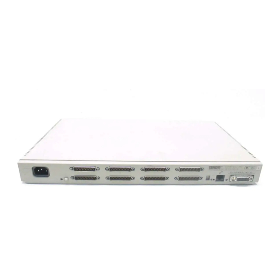
- Page 2 EK-DSRVW-IN.001 DECserver 700 Hardware Installation Card Rear View DECserver 700-16 Rear View DECserver 700-08 LKG-5809-91l...
- Page 3 Check the Contents of the Box If any part is damaged or missing, contact your Digital Equipment Corporation sales representa- tive. Power cord DECserver 700 Site Preparation and Maintenence Software license Installation Card Server feet FTZ card (Austria/ Germany only,...
- Page 4 Verify the Site Verify that: 1. The devices (modems, printers, PCs, and termi- nals) and their cables are installed. 2. An Ethernet cable is installed. 3. A power socket is available within 1.8 meters (6 feet) of the server position. 4.
- Page 5 Place the Server – Racks 1. Install the nuts. LKG-5813-91l 2. Install the brackets. LKG-5814-91l...
- Page 6 Place the Server – Racks (Cont.) 3. Install the server in the rack. LKG-5815-91l NOTE This is the most common method of installing the server in a rack. Refer to DECserver 700 Site Preparation and Maintenance, Chapter 3, for other methods.
- Page 7 Connect Device Cables to DECserver 700-08 Server Caution The V24/RS-232-C adapter (12-27591-01) (not supplied) must be fitted between the server and the extension cable if the modem/elimina- tor has Data Signal Rate Selector (DCE) on pin 23 (refer to modem manual). 1.
- Page 8 2. If the adapter is not needed, insert the 25-pin D-connector and tighten the screws. LKG-5818-91l Connect Device Cables to DECserver 700-16 Server LKG-5819-91l...
- Page 9 Connect the Ethernet Port You may connect your server to standard, 10BaseT, or ThinWire Ethernet. To connect to standard Ethernet: 1. Turn the Ethernet select switch to the right to select standard Ethernet. LKG-5820-91l 2. Unlock the Ethernet connector by Unlock sliding the latch to the right.
- Page 10 To connect to 10BaseT Ethernet: 1. Turn the Ethernet select switch to the left to select 10BaseT Ethernet. LKG-5824-91l 2. Insert the cable. LKG-5811-91l To connect to ThinWire Ethernet: 1. Turn the Ethernet select switch to the right to select standard Ethernet. LKG-5825-91l...
- Page 11 To connect to ThinWire Ethernet (Cont.): 2. To connect to ThinWire Ethernet, you must install a media access unit (MAU) which is not supplied. a. Insert the MAU. b. Insert the ThinWire cable. ThinWire cable LKG-5826-91l Connect Power to Server LKG-5827-91l...
- Page 12 Verify Server Is Operating Correctly When you plug in the power cable, the server runs tests. After the tests are completed, the server requests a down-line load of software. The 7-segment display alternates between 3 and 4 until the software is loaded. Allow 3 minutes for the server to complete the proce- dure.
- Page 13 700 Site Preparation and Maintenance for further action. Check that the power cable is installed cor- rectly and that power is available. Refer to DECserver 700 Site Preparation Maintenance if checks show power is avail- able. FLASHING Server has failed self- test.
Need help?
Do you have a question about the DECserver 700 and is the answer not in the manual?
Questions and answers