Table of Contents
Advertisement
Quick Links
Advertisement
Table of Contents

Subscribe to Our Youtube Channel
Related Manuals for Garmin CS 1522


Summary of Contents for Garmin CS 1522
- Page 1 CS 1522 Professional Fishfinder Owner’s Manual...
- Page 2 All rights reserved. Under the copyright laws, this manual may not be copied, in whole or in part, without the written consent of Garmin. Garmin reserves the right to change or improve its products and to make changes in the content of this manual without the obligation to notify any person or organization of such changes or improvements.
-
Page 3: Table Of Contents
TABLE OF CONTENTS CHAPTER 1 INTRODUCTION ������������������������������������������������������������������������� 5 A Brief History of Sonars ....................5 1.1.1 Basic Principles of Sonars ..................5 1.1.2 Development of Sonars .................... 5 1.1.3 Determining the Distance ..................5 1.1.4 Locating Fish on a Sonar Display ................6 Specifications ........................6 1.2.1 NMEA 2000 PGN Information .................. - Page 4 1.8.2 Updating the Software .................... 27 Protective Cover ......................27 1.10 Garmin Support Center ....................28 1.10.1 Registering Your Device ..................28 CHAPTER 2 GETTING STARTED ����������������������������������������������������������������� 29 Basic Operations ......................29 2.1.1 Powering On/Off ..................... 29 2.1.2 Stopping the Transmission of the Transducer ............29 2.1.3...
- Page 5 CHAPTER 3 MENU AND SETTINGS ������������������������������������������������������������� 43 Accessing the Menu .......................43 Sonar Setup ........................43 3.2.1 Adjusting Gain ......................43 3.2.2 Adjusting Contrast ....................44 3.2.3 Adjusting Frequency ....................44 3.2.4 Adjusting Range ...................... 44 3.2.5 Adjusting Zoom ...................... 44 3.2.6 Adjusting Shift ......................44 3.2.7 Adjusting Scroll Speed ...................
- Page 6 Quickdraw Contours ......................55 3.9.1 Mapping a Body of Water ..................55 3.9.2 Adding a Label to a Quickdraw Contours Map ............. 55 3.9.3 Garmin Quickdraw Contours Settings ..............56 3.9.4 Garmin Quickdraw Community ................56 3.10 Navigation Chart Appearance ..................58 3.10.1 Customizing Chart Layers ..................
-
Page 7: Chapter 1 Introduction
CHAPTER 1 INTRODUCTION WARNING See the Important Safety and Product Information in the Installation Instructions for product warnings and other important information. You are responsible for the safe and prudent operation of your vessel. Sonar is a tool that enhances your awareness of the water beneath your boat. It does not relieve you of the responsibility of observing the water around your boat as you navigate. -
Page 8: Locating Fish On A Sonar Display
1.1.4 Locating Fish on a Sonar Display The beam of sound transmitted from the transducer spreads wider as it passes into deeper water, forming a conical shape under the boat. As a fish crosses the cone, the distance between the fish and the transducer would be marked on the sonar display, and since the center of the cone is closest to the transducer, a fish that swims through the cone at a constant depth would form an arch on the sonar display. 1�2 Specifications Specification Measurement Dimensions (W x H x D) 355 x 376.7 x 82.7 mm... -
Page 9: Nmea 2000 Pgn Information
**** The device is protected against powerful jets of water, and withstands incidental exposure to water of up to 1 m for up to 30 minutes. For more information on water rating, go to Garmin.com/waterrating. 1.2.1 NMEA 2000 PGN Information... -
Page 10: Nmea 0183 Information
Type Description Receive 127508 Battery status 129038 AIS class A position report 129039 AIS class B position report 129040 AIS class B extended position report 129539 GNSS DOPs 129794 AIS class A static and voyage related data 129809 AIS class B “CS” static data report, part A 129810 AIS class B “CS”... -
Page 11: Inside The Box
Type Sentence Description Receive Water speed and heading Waypoint location Digital selective calling information Expanded digital selective calling Heading, deviation, and variation Heading, magnetic Wind direction and speed Meteorological composite Wind speed and angle AIS VHF data-link message You can purchase complete information about National Marine Electronics Association (NMEA) format and sentences from: NMEA, Seven Riggs Avenue, Severna Park, MD 21146 USA (www.nmea.org). -
Page 12: Device Overview
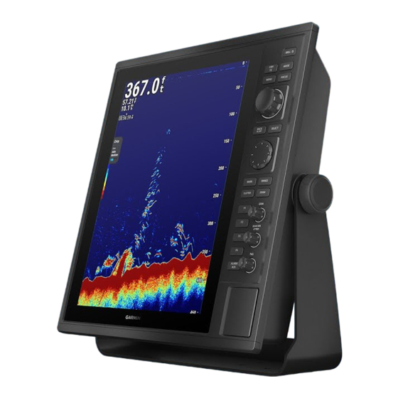
Flush mount template 190-02655-03 Documentation K00-01227-01 1.3.1 Device Overview The Garmin CS 1522 features a 15-inch XGA display, with a control panel, and 2 SD card slots on the side. The CS 1522 can be bail mounted or flush mounted to your boat. Connection to a transducer such as GT40-TM, is required. 378.3 mm 108.3 mm CHAPTER 1 INTRODUCTION... -
Page 13: Ports
1�3�2 Ports The ports are located at the back of the device. POWER 12-PIN XDCR NMEA 0183 GPS ANT NMEA 0183 GSD SONAR NMEA 2000 Ground 1.3.3 Port Pin Definition Power Port Accessory NMEA TXB NMEA RXB Power supply - / Ground Power supply + NMEA TXA Alarm... -
Page 14: Installation
When drilling or cutting, always check what is on the opposite side of the surface. Read all installation instructions before proceeding with the installation. If you experience difficulty during the installation, contact Garmin support. 1.4.1 Typical Configuration The diagram shows a typical configuration of the device. NMEA 0183 Network GPS Antenna CS 1522 Rectifier 10–36 VDC 115/230 VAC Transducer Transducer Power Supply Power Supply 1.4.2 Tools Needed •... -
Page 15: Mounting Considerations
1.4.3 Mounting Considerations NOTICE This device should be mounted in a location that is not exposed to extreme temperatures or conditions. The temperature range for this device is listed in the product specifications. Extended exposure to temperatures exceeding the specified temperature range, in storage or operating conditions, may cause device failure. Extreme- temperature-induced damage and related consequences are not covered by the warranty. -
Page 16: Flush Mounting The Device
5 Place the device in the bail-mount and tighten the bail mount knobs. 1.4.5 Flush Mounting the Device NOTICE Use the included template and hardware to flush mount the device in your dashboard. Be careful when cutting the hole to flush mount the device. There is only a small amount of clearance between the case and the mounting holes, and cutting the hole too large could compromise the stability of the device after it is mounted. 1 Trim the template, and make sure it fits in the location you want to mount the device. - Page 17 If you are using a nut plate, the smaller hole on the nut plate should line up with the smaller hole on the template. 12 If the smaller hole on the nut plate does not line up with the smaller hole on the template, mark the new hole location.
-
Page 18: Thru-Hull Transducer Installation
Thru-Hull Transducer Installation WARNING After installation, check your boat for leaks before leaving it in the water for an extended period of time. CAUTION Always wear safety goggles, ear protection, and a dust mask when drilling, cutting, or sanding. Do not install a transducer in the engine compartment or near heat sources. NOTICE When drilling or cutting, always check what is on the opposite side of the surface. -
Page 19: Fairing Block Angle Cut
When selecting a mounting location, observe these considerations: • On outboard and sterndrive vessels , the transducer should be mounted in front of and close to the engine or engines. • On inboard vessels , the transducer should be mounted in front of and far away from the engine propeller and shaft. -
Page 20: Cable Considerations
When installing the cables, you should observe these considerations: • Cutting the Garmin Marine Network cable is not recommended, but a field install kit can be purchased from Garmin or a Garmin dealer if cutting the network cable is necessary. -
Page 21: Connecting The Wiring Harness To Power
Item Wire Color Wire Function Power supply + Black Power supply - / Ground (power supply and NMEA 0183) Blue NMEA 0183 TXA Brown NMEA 0183 RXA Gray NMEA 0183 TXB Violet NMEA 0183 RXB Orange Accessory on Yellow Alarm low 1.6.2 Connecting the Wiring Harness to Power WARNING... -
Page 22: Gps Antenna Considerations
• Connect the antenna to the GPS ANT port. 1.6.4 Connecting the Device to a Transducer Devices that can receive depth information from a Garmin transducer have a port labeled 12-PIN XDCR. Go to www.garmin.com or contact your local Garmin dealer to determine the appropriate type of transducer for your needs. -
Page 23: Nmea 0183 Connection Considerations
(TX port) on the included NMEA 0183 data cable. You can connect one NMEA 0183 device to the internal RX port to input data to this Garmin device, and you can connect up to three NMEA 0183 devices in parallel to the internal TX port to receive data output by this Garmin device. - Page 24 • The internal NMEA 0183 ports and communication protocols are configured on the connected Garmin device. See the NMEA 0183 section of the chartplotter owner’s manual for more information. NMEA 0183 Device Connections This diagram illustrates two-way connections for both sending and receiving data.
- Page 25 Single-Ended NMEA 0183 Device Connections Item Description Power source Power / NMEA 0183 cable NMEA 0183 device NMEA 0183 Device Item Garmin Wire Color Garmin Wire Function Wire Function Power Power Black Power ground Power ground Violet Brown Blue Gray •...
- Page 26 In this example, the NMEA 0183 device is sending data to the chartplotter. Item Description DC Power supply / battery Power / NMEA 0183 cable NMEA 0183 device NMEA 0183 Device Item Garmin Wire Color Garmin Wire Function Wire Function Power Power Black Power ground Power ground...
-
Page 27: Lamp And Horn Connections
1.6.8 Lamp and Horn Connections The device can be used with a lamp, a horn, or both, to sound or flash an alert when the chartplotter displays a message. This is optional, and the alarm wire is not necessary for the device to function normally. When connecting the device to a lamp or horn, observe these considerations. • The alarm circuit switches to a low-voltage state when the alarm sounds. •... -
Page 28: Control Panel
1�7 Control Panel Press: Turns power on; adjusts the backlight. Hold: Turns power off. Press: Disables or enables sonar Press: Selects display modes. transmission. Press: Moves focus (highlight) to Press: Opens or closes the menu. the next option. Turn: Adjusts the range in sonar modes;... -
Page 29: Capturing A Screenshot
2 Open the downloaded file, and follow the on-screen instructions to copy the software update to an SD card. A Garmin folder containing the software update is created on the SD card. 3 Power on the device, and insert the SD card into one of the card slots. NOTE: In order for the software update instructions to appear, the device must be fully booted before the card is inserted. -
Page 30: 1.10 Garmin Support Center
The device creates a file named GarminDevice.xml in the Garmin folder on the SD card. 3 Remove the SD card. 4 Insert the SD card into your computer. 5 On your computer, go to my.garmin.com. 6 Follow the on-screen instructions to download, install, and open the Garmin Express application. 7 Select Add a Device. -
Page 31: Chapter 2 Getting Started
2.1.1 Powering On/Off Press [ ] to turn on the device. The GARMIN logo appears, and the control panel lights up, and a sonar view of the water under your boat shows up on screen. To turn the power off, hold [ ] until the GARMIN logo appears. -
Page 32: Display Modes
Display Modes 2.2.1 Typical Views The following views are typical examples of how each display mode looks like. Traditional 2-Split Frequency 4-Split Frequency Traditional mode shows a 2-Split Frenquency mode 4-Split Frenquency mode large image of the sonar shows two split screens with shows four split screens with readings from a transducer. -
Page 33: Sonar Interface Overview
2.2.2 Sonar Interface Overview The following is an overview of the sonar interface, using the Traditional mode as an example. 85�2 Bottom depth Range scale Water temperature 58�29 Speed 10�1 Unit voltage 11�8 Time 07:45:55 Fish symbol Transducer model B265LH Operating Chirp frequency... -
Page 34: Adjusting The Range
CHIRP sonar sends a continuous sweep of frequencies ranging from low to high. Garmin CHIRP sonar technology then interprets each frequency individually upon its return. This provides much more information, from which CHIRP sonar is able to construct a much clearer, higher resolution image with greater target separation and crisper fish arches. - Page 35 No Zoom Select No Zoom to view the full range from 0 to the set depth range (see 2.3.2). Auto Zoom 85�2 Select Auto Zoom for a magnified view that is locked to the bottom. This is useful for 58�29 determining the bottom contour. 10�1 11�8 1 Press [ZOOM] > Auto Zoom. 07:45:55 2 Press up/down to adjust the Zoom (width of view). Chirp Gain Zoomed view...
- Page 36 3 Press [SELECT] to confirm the adjustment. Shift Zoom Select Shift Zoom to view the specified range with higher accuracy and detail with the unique sonar zoom technology from Garmin. In this mode the device only processes the sonar signals received from the selected depth range. NOTE: Not available in ClearVü and SideVü modes. 1 Press [ZOOM] > Shift Zoom.
-
Page 37: Hiding Overlay Data And Depth Scale
Split Zoom Select Split Zoom to toggle a split screen on/off and opens the Sonar Zoom menu. You can continue to select a second zoom option for the split screen on the left, keeping the original zoom option on the right. NOTE: Not available in Split Frequency modes. -
Page 38: Adjusting Contrast
2.4.3 Adjusting Contrast In ClearVü and SideVü modes, you can increase the contrast to highlight smaller fish targets or create a higher intensity display of a target. This causes a loss in the differentiation of the high intensity returns at the bottom. You can reduce the contrast if you want to reduce the intensity of the returns. -
Page 39: Selecting Split Screens
2.5.2 Selecting Split Screens Split screens in the 2-Split Frequency and 4-Split Frequency modes can be adjusted individually. • Press [FOCUS] to sequentially highlight split screens. The highlighted split screen is automatically selected. • Press [BACK] to cancel the highlight. The selection is remembered until you switch to another mode. -
Page 40: Marking A Waypoint
2.5.4 Marking a Waypoint • To mark your boat position as a waypoint, press [MARK] without invoking the cursor. • To mark previous positions and depths, move the cursor to a previous position, and either press [MARK] or press [SELECT] > New Waypoint. •... -
Page 41: Navigation Chart
Navigation Chart CAUTION The navigation feature does not ensure obstacle and bottom clearance. Carefully compare the course to all visual sightings, and avoid any land, shallow water, or other obstacles that may be in your path. The Navigation Chart mode allows you to view your vessel on preloaded or purchased charts and navigate to your destination. -
Page 42: Viewing Information
Creating a Route to a Destination 1 Use the control pad to move the cursor to a point you would like to navigate to. 2 Press [SELECT] > Route To. to create a route with turns to the destination. 3 Use the control pad to move the cursor to the final turn, and press [SELECT] > Add Turn. -
Page 43: F1-F4 Shortcuts
F1-F4 Shortcuts The F1 to F4 shortcut buttons are assigned to various functions for quick accesses. Mode Traditional A-Scope 2-Split Frequency Fish Symbols Beam Coverage 4-Split Frequency Frequency Scroll Speed ClearVü Surface Noise Depth Line SideVü View Selection Navigation Chart Go To Route To Active Track 2.7.1... - Page 44 CHAPTER 2 GETTING STARTED...
-
Page 45: Chapter 3 Menu And Settings
CHAPTER 3 MENU AND SETTINGS Accessing the Menu The menu contains more advanced or less frequently used features and settings. • From any screen, press [MENU] to open the menu. • Use the main knob and the control pad to scroll through the menu. •... -
Page 46: Adjusting Contrast
3.2.2 Adjusting Contrast You can control the level of contrast in ClearVü and SideVü modes to change the intensity of returns (see 2.4.3 for more information). Select Contrast and make a selection: • Manual allows you to adjust the contrast manually using the main knob or the control pad. -
Page 47: Adjusting Bottom Search Limit
Select Scroll Speed and make a selection: • Manual allows you to adjust the scroll speed manually using the main knob or the control pad. TIP: Adjust to a slower speed to avoid gaps appearing in the seafloor. Slow Fast Scroll Speed Menu Sonar Setup Sonar Setup Gain Manual Frequency Auto Clutter Alarms Range Default... -
Page 48: Reducing Interference
3.3.1 Reducing Interference You can adjusts the sensitivity to reduce the effects of interference from nearby sources of noise. Interference from other acoustic or electronic equipment operating nearby may appear on the display. Minor interference or noise can be stray signals that look like actual targets. Severe noise can completely fill the screen and make depth readings impossible. To counter interference, you have to first identify the type of interference. -
Page 49: Reducing Surface Noise
3.3.5 Reducing Surface Noise You can enable this setting to reduce clutter near the surface. Noise may appear near the surface when the sea is rough or when your boat passes over a wake. Wider beam widths can also result in more surface noise. 60�1 Surface noise N 25°45�563'... -
Page 50: Alarms
Alarms Press [MENU] > Alarms to set up multiple alarms that will sound when the set conditions are met. Menu Alarms Shallow Water Sonar Setup Clutter Change Depth 12.0 Alarms Deep Water Navigation Info Change Depth 100.0 Appearance Water Temperature Settings Lower Limit 50.0... -
Page 51: Setting Fish Alarms
3.4.5 Setting Fish Alarms The fish alarm will sound when fish of different sizes are detected. Select Fish and choose one of the settings: • Select Off to turn the alarm off. • sets the alarm off when fish of all sizes are detected. • sets the alarm off when medium or large fish are detected. •... -
Page 52: Sonar Appearance
4 Use the control pad to move the cursor to the next point, or the rim of the circle. 5 Press [SELECT] > Add Point / Set Radius to confirm the position. 6 For Line or Area, continue to add points until the boundary is complete. 7 Use the main knob, select Done to create the boundary. -
Page 53: Selecting Views In Sidevü Mode
• Select Overlay Data > Color Bar to show/hide the color bar (only available in Traditional and Split Frequency modes). • Select Overlay Data > Transducer Model to show/hide the transducer model. • Select Depth Line to show/hide the depth line with a depth indicator, you can move the depth line with the control pad. -
Page 54: Selecting The Chart Orientation
3.6.1 Selecting the Chart Orientation The chart can be oriented in three different ways. Select Orientation and select an option: • Select Head Up to orient the chart so the heading always points straight up. • Select North Up to orient the chart so north always points straight up. •... -
Page 55: Managing Tracks
3.7.3 Managing Tracks A track is a recording of the path of your boat. The track being recorded is the active track. Select Tracks and choose one of the settings: • Select Active Track Options to toggle on active tracking. With the option toggled on: •... -
Page 56: Ais
3.8.2 With the Automatic Identification System (AIS), the device identifies and tracks other vessels, and alerts you to area traffic. The device shows AIS information about vessels within range equipped with a transponder, and are actively transmitting AIS information. Targets are indicated on the display with targeting symbols. Symbol Description AIS vessel. The vessel is reporting AIS information. The direction of the triangle indicates the direction the AIS vessel is moving. Selected target. -
Page 57: Quickdraw Contours
It is estimated that you might be able to record about 1,500 hours of data onto a 2 GB memory card. When you record data on a memory card, the new data is added to your existing Garmin Quickdraw Contours map, and is saved on the memory card. When you insert a new memory card, the existing data does not transfer onto the new card. -
Page 58: Garmin Quickdraw Contours Settings
3.9.4 Garmin Quickdraw Community The Garmin Quickdraw Community is a free, public, online community that enables you to share your Garmin Quickdraw Contours maps with others. You can also download maps other users have created. To access the Garmin Quickdraw Community, sign in to your Garmin Connect™ account. - Page 59 2 Access the Garmin Quickdraw Community. 3 Use the map and search features to locate an area to download. 4 The red dots or lines represent Garmin Quickdraw Contours maps that have been shared in that region. 5 Click Select an Area to Download and agree to the end-user license agreement.
-
Page 60: 3.10 Navigation Chart Appearance
3.10 Navigation Chart Appearance Press [MENU] > Appearance in Navigation Chart mode to customize the appearance of your navigational chart. NOTE: The menu is specific to Navigation Chart mode. Menu Appearance Chart Setup Chart > Navigation Info My Vessel > Other Vessels Waypoints Alarms Boundaries Quickdraw Contours Tracks >... -
Page 61: 3.11 Settings
3.11 Settings Settings below are for system-wide settings, device and software information, user preferences, and vessel information. 3.11.1 System Settings Press [MENU] > System to adjust system-wide settings. Menu System Settings Sounds and Display > System System Information Preferences > Auto Power Up Communications 0�55... -
Page 62: 3.11.3 Communications Settings
3.11.3 Communications Settings Press [MENU] > Communications to adjust marine network settings. Menu Communications Settings NMEA 0183 Setup > System NMEA 2000 Setup > Preferences Marine Network Communications My Vessel Data Management Installation • Select NMEA 0183 Setup to change NMEA 0183 port and device settings. •... -
Page 63: Chapter 4 Echo Patterns
CHAPTER 4 ECHO PATTERNS There are other non-fish objects that reflect or block sonar beams. They form different patterns on the sonar screen. Learn to recognize these patterns to avoid misinterpreting them as fish schools. Surface Noise Surface noise appear near the top of the screen when the sea is rough or when your boat passes over a wake. The effect can be reduced in the Clutter menu (see 3.3.1). Surface noise Colliding Currents When two ocean currents of different temperature and direction collide, they form eddies... -
Page 64: Plankton Layers
Plankton Layers Layers of concentrated planktons of up to a few meters thick appear as a cloud of dots. They tend to rise up to the surface in the day and fall to deeper waters in the night. Plankton Air Bubbles Air bubbles in the water can block sound waves, causing gaps in the water bottom. -
Page 65: Chapter 5 Appendices
Unsupported Transducer sure a compatible transducer is connected and that Connected settings are configured accordingly. If problems persist, contact Garmin Support. Check the power and network connections on the Sonar module lost: (device) external sonar module and the sonar display. Hazardous Substance Table 产品中有害物质的名称及含量... -
Page 66: Declaration Of Conformity
97080 Würzburg, Germany Type of Equipment: Portrait Radar/Sonar Display Model Number(s): A03785 (CR 1522, CR 1523, CS 1522, CS 1523) The undersigned does hereby declare that the equipment complies with the above Directives Jamie Wiltshire Quality Supervisor Garmin (Europe) Ltd. -
Page 67: Menu Tree
Menu Tree - Gain - Contrast (ClearVü/SideVü) - Frequency - Range - Zoom Sonar Setup (Sonar) - Shift (Not in SideVü) - Scroll Speed - Bottom Search Limit (Not in SideVü) - Sonar Recording - Transmit - Interference - Color Limit (Traditional) - Color Filter (Traditional) Clutter (Sonar) - Smoothing (Traditional) - Page 68 - Navigate To Position (Chart) - Waypoints - Record Mode - Active Track Options - Interval - Track Color - Save Active Track - Tracks - Clear Active Track - Follow Active Track Navigation Info - Saved Tracks - Routes - Boundaries - Tides - Tides &...
- Page 69 - Navigation - Compass Tape - Beeper - Sounds and Display - Backlight - Color Mode - GPS - Garmin Devices - Reset Default Settings - Reset System - Delete User Data - System Information - Software Information - Event Log...
- Page 70 - NMEA Output 1 - NMEA Output 2 - Sounder - Router - Output Sentences - System - NMEA 0183 Setup - Garmin - Position Precision - XTE Precesion - Waypoint IDs - MMSI - Restore Defaults Communications - Diagnostics...
- Page 71 - File Type - Save to Card - Data Transfer - Merge from Card - Replace from Card - Delete File - User Data - Waypoints - Routes Data Management - Active Track - Delete User Data - Saved Tracks - Owner’s Manual - Boundaries - Delete All User Data...
- Page 72 CHAPTER 5 APPENDICES...
- Page 74 Garmin International, Inc. 1200 East 151st Street, Olathe, Kansas 66062, USA Garmin (Europe) Ltd. Liberty House, Hounsdown Business Park, Southampton, Hampshire, SO40 9LR, UK Garmin Corporation No. 68, Zhangshu 2nd Road, Xizhi Dist., New Taipei City, 221, Taiwan R-R-GRm-A03785 M/N: A03785...
Need help?
Do you have a question about the CS 1522 and is the answer not in the manual?
Questions and answers