
Related Manuals for 3M Fibrlok II 2529


Summary of Contents for 3M Fibrlok II 2529
- Page 1 Fibrlok II 2529 ™ Universal Optical Fiber Splice Instructions January 1994 Issue 1, 34-7035-4458-4...
-
Page 2: Table Of Contents
Contents: General ............................... 3 Splicing Set-up ........................... 4 Fiber Preparation ..........................5 Splice Assembly ..........................6 Fiber Repositioning ..........................8 Fiber Organization and Splice Storage ....................9 Splicing Accessories ........................... 11... -
Page 3: General
250 m to 900 m. 1.02 All Fibrlok ™ II 2529 Universal Optical Fiber Splices are gray in color and are marked with the 3M Fibrlok ™ II logo on the splice cap. End Plug (each end) 1.50"... -
Page 4: Splicing Set-Up
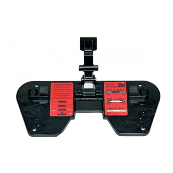
1.05 Some Compatible Organizers are: ™ • Fibrlok 2500 or 2501 Assembly Tool • 3M 2118, 3M 2524, 3M 2672 • Plastic Coating (Buffer) Stripper • AT&T UC-SS/M1 • Reagent Grade Isopropyl Alcohol • GTE Part 910470 0000, 910470 1000 •... -
Page 5: Fiber Preparation
2.05 If using the Fibrlok 2501 Assembly Tool, rotate the toggle arms for the appropriate fiber size. Inward – 250 m Outward – 900 m Fiber Preparation 3.01 Remove the minimum length of fiber required to prepare and splice the fibers. 1"... -
Page 6: Splice Assembly
3.05 Check the cleave length using the 12.5 mm cleave length gauges on the Fibrlok Assembly Tool. Adjust the cleaver to provide the prescribed cleave lengths. Check cleave lengths periodically during subsequent splicing operations. Note: Do not allow cleaved end to contact tool. Do not clean 250 µm 900 µm the fibers again after they have been cleaved. - Page 7 4.03 Gently continue pushing the fiber into the splice until resistance is felt. When fully inserted, the first fiber should be straight or have a slight bow – up to .1 inch (3 mm). Note: If properly inserted, bare glass should not be visible outside of splice.
-
Page 8: Fiber Repositioning
4.09 Pivot the handle of the Fibrlok Assembly Tool down until it contacts the cap of the Fibrlok Splice. Squeeze the handle of the assembly tool as shown in order to close cap and actuate the splice. When possible, secure the tool to a work surface for added support. -
Page 9: Fiber Organization And Splice Storage
5.04 Hold the cap lifter in place with one hand and push down on the ends of the splice with the other hand. This action should reseat the splice into the holding cradle and lift the cap at the same time. 5.05 Repeat fiber centering and splice actuation (See step 4.06 –... - Page 10 6.05 Remove the minimum amount of fiber required for fiber preparation and splicing. Remove less than one loop if possible. 6.06 Prepare fibers and complete splice as described in Section 3 and 4. 6.07 Carefully lay the splice on top of the holder without securing the splice into the holder.
-
Page 11: Splicing Accessories
7.02 The 2524 Splice Tray fits and mounts into the 3M 2177 Fiber Optic Splice Closure, the 3M 2178 Fiber Optic Splice Case and the 3M 2190 PST Fiber Optic Splice Closure. It is also compatible with a variety of non-3M closures. - Page 12 LIMITED TO NEGLIGENCE OR STRICT LIABILITY, FOR ANY INJURY OR FOR ANY DIRECT OR CONSEQUENTIAL DAMAGES SUSTAINED OR INCURRED BY REASON OF THE USE OF ANY OF THE SELLER'S PRODUCTS THAT WERE DEFECTIVE. Telecom Systems Division 6801 River Place Blvd. Austin, TX 78726-9000 Printed in USA 800/426-8688 © 3M 1994 34-7035-4458-4...
Need help?
Do you have a question about the Fibrlok II 2529 and is the answer not in the manual?
Questions and answers