Advertisement
Quick Links
3M
Fibrlok
™
Fiber Splice 2529
Instructions
1.0 General
1.1
The 3M
Fibrlok
II Universal Optical Fiber Splice
™
™
2529 provides permanent mechanical splices for
single- or multimode fiber having 125 μm diameter
cladding. The 2529 universal splice is designed
to accommodate any combination of fibers with
coating diameters from 250 μm to 900 μm.
1.2
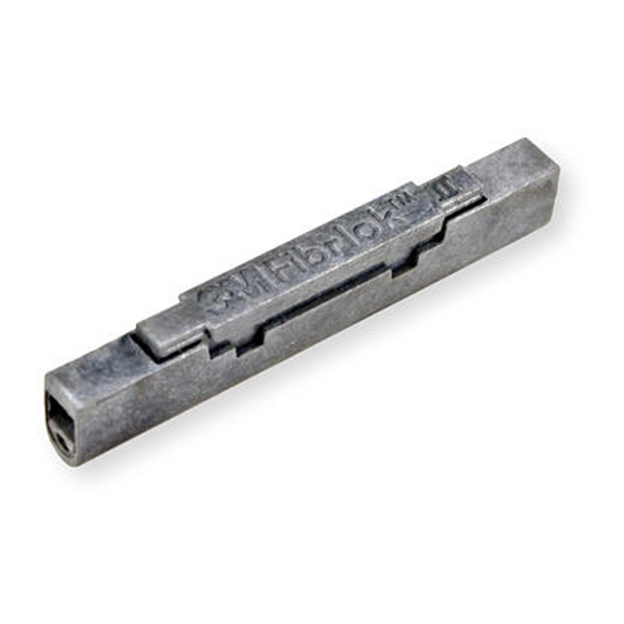
All Fibrlok 2529 splices are gray in color and
are marked with the 3M Fibrlok II logo on the
splice cap.
December 2015
78-8128-0163-3-H
3M Fibrlok II Specs
Provided by www.AAATesters.com
II Universal Optical
™
1.50" (38.1 mm)
.150"
(3.8 mm)
End Plug
(each end)
Jacket
Fiber Entry Port
(each end)
0.250"
(6.4 mm)
Cap
Advertisement

Related Manuals for 3M Fibrlok II


Summary of Contents for 3M Fibrlok II
- Page 1 250 μm to 900 μm. All Fibrlok 2529 splices are gray in color and are marked with the 3M Fibrlok II logo on the splice cap. End Plug (each end)
- Page 2 Fiber retention pad Fiber retention pad Toggle arm Toggle arm Finger cutout Instruction label (2) Fiber cleave length gauge Mounting holes (4) Base (both ends of tool) Some compatible 3M Fiber Splice Tray product ™ numbers are: 2522, 2524, 2523, 2527.
-
Page 3: Splicing Set-Up
Skin Contact: Wash with soap and water. Production Information Source: Safety Data Sheet or 3M Company, St. Paul, MN 55144-1000, (612) 733-111-: Operator 55 Note: Storage, use and disposal of isopropyl alcohol should be per your company health, safety and environmental instructions. -
Page 4: Fiber Preparation
Note: The stripper should be in good operating condition the 3M Fibrlok Splice. to prevent scratches or other damage to the glass cladding. Check the cleave length using the 12.5 mm cleave length gauges on the 3M Fibrlok Assembly Tool ™ ™... - Page 5 78-8128-0163-3-H December 2015 4.0 Splice Assembly Push the fiber down into the fiber retention pad on the proper side of the splice. Note: Hold the coated portion of the fiber ONLY. Do not allow the cleaved end to contact any surface before insertion into the splice. Gently continue pushing the fiber into the splice until resistance is felt.
- Page 6 Push the first fiber back against the second fiber until there are equal bows in both fibers. Note: Do not pull on either of the fibers following 4.10 Remove the 3M Fibrlok Splice from the assembly establishment of the bows in the first and second tool by first removing the fibers from the foam fibers. The fiber ends must be held together by the...
- Page 7 78-8128-0163-3-H December 2015 5.0 Fiber Repositioning If high loss is observed after splice has been actuated, it is possible that the fiber ends are separated. In this case, lift the splice cap and reposition fiber ends, as instructed below. Note: Do not completely remove fiber from Fibrlok Splices.
- Page 8 December 2015 78-8128-0163-3-H For 250 to 250 µm and 900 to 900 µm splices: a. Store the shorter of the two fibers in the tray. b. Observe how the splice lays in its relaxed state. Rotate the splice through the smallest possible angle to install it in the tray.
- Page 9 900 µm coated fibers) and can be adapted for fusion splice storage. The 3M Fiber Splice Organizer Tray 2524 splice ™ tray fits and mounts into the 3M Fiber Optic ™ Splice Closure 2178. It is also compatible with a variety of non-3M closures.
- Page 10 Warranty; Limited Remedy; Limited Liability. This product will be free from defects in material and manufacture for a period of one (1) year from the time of purchase. 3M MAKES NO OTHER WARRANTIES INCLUDING, BUT NOT LIMITED TO, ANY IMPLIED WARRANTY OF MERCHANTABILITY OR FITNESS FOR A PARTICULAR PURPOSE.
Need help?
Do you have a question about the Fibrlok II and is the answer not in the manual?
Questions and answers