Advertisement
Quick Links
100 - 240V~
47-63Hz ~ 25W MAX
FUSE: T500mAL
WARNING
THIS APPARATUS MUST BE EARTHED.
ATTENTION: REMPLACER LE FUSIBLE AVEC UN DES MEMES CARACTERISTIQUES.
FOR CONTINUED PROTECTION AGAINST RISK OF FIRE REPLACE FUSE WITH SAME TYPE AND RATING.
CAUTION: RISK OF ELECTRIC SHOCK. DO NOT OPEN.
AVIS: RISQUE DE CHOC ELECTRIQUE - NE PAS OUVRIR.
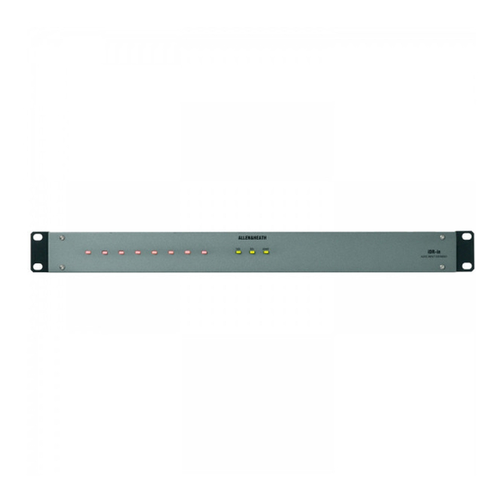
iDR-in and iDR-out are add-on audio expander units for the Allen & Heath iDR-4 and iDR-8 audio mix processors.
They provide additional analogue audio inputs and outputs to add to those on the main unit. The iDR-in has 8 mic/line
inputs, the iDR-out has 8 line outputs. One or both may be connected to the iDR. Only one of each may be added to
the iDR system bringing it up to a maximum 16x16 audio matrix. These units do not have any processing built in. They
simply convert between analogue and digital audio to work with an 8 channel wide digital bus which feeds the main
unit via a CAT5 STP cable. The iDR-in features high grade mic/line preamps with PC configured gain, pad and
phantom power switching, and a built-in soft clip limiter. The iDR-out provides electronically balanced differential
outputs. The processing is available on the main iDR-4 or iDR-8 unit which features the full 16x16 DSP matrix. Both
units have 8 front panel LEDs in addition to the 3 status indicators. These are 3-colour soft LEDs which can be
assigned as audio meters, mute indicators or patch related indicators. They are programmed in the usual way using
the iDR System Manager software. Control of the expanders is via the DR-Link port using a CAT5 STP cable. This
means that two CAT5 cables are required to interconnect an expander to the main unit. Maximum distance between
the units is 250 metres. Local mains power is required.
NOTE:
parts inside. Any changes or modifications to the equipment not approved by
Allen & Heath could void the compliance of the equipment and therefore the
users authority to operate it.
Whilst we believe the information in this guide to be reliable we do not assume
responsibility for inaccuracies. We also reserve the right to make changes in
the interest of further product development.
iDR-in/out User Guide AP4774
iDR-in/out EXPANDER
EXPANDER INPUTS
next
previous
OUT DR-LINK
IN
AUDIO OUT
SERIAL NUMBER
DIGITAL EXPANDER
Made in the UK by ALLEN&HEATH LIMITED
Complies with UL6500, CSA-E65, EN60065
EXPANDER OUTPUTS
next
previous
OUT DR-LINK
IN
AUDIO IN
SERIAL NUMBER
DIGITAL EXPANDER
Made in the UK by ALLEN&HEATH LIMITED
Complies with UL6500, CSA-E65, EN60065
This product complies with the European Electromagnetic
Compatibility directives 89/336/EEC & 92/31/EEC and the
European Low Voltage Directives 73/23/EEC & 93/68/EEC.
Do not remove the cover of the unit. There are no user serviceable
iDR-in/out User Guide AP4774 Issue 2
Copyright © 2003 Allen & Heath Limited. All rights reserved
User Guide
lock
link
power
lock
link
power
IN 8
IN 7
OUT 8
OUT 7
IN 6
IN 5
IN 4
IN 3
MIC/LINE INPUTS
OUT 6
OUT 5
OUT 4
OUT 3
LINE OUTPUTS
AP4774
iDR-in
AUDIO INPUT EXPANDER
iDR-out
AUDIO OUTPUT EXPANDER
IN 2
IN 1
OUT 2
OUT 1
1
Advertisement

Related Manuals for ALLEN & HEATH iDR-in


Summary of Contents for ALLEN & HEATH iDR-in
- Page 1 Allen & Heath iDR-4 and iDR-8 audio mix processors. They provide additional analogue audio inputs and outputs to add to those on the main unit. The iDR-in has 8 mic/line inputs, the iDR-out has 8 line outputs.
- Page 2 The iDR-in and iDR-out expanders can be rack mounted or free standing. There are no user controls on the front panel, only the status and assignable LEDs. Allow a minimum of 75mm clearance behind the unit for the connectors and cables.
- Page 3 IN OUT either or both expanders according to the requirements of your application. The iDR-in AUDIO OUT connects to the iDR-4(8) AUDIO IN. The iDR-out AUDIO IN connects to the iDR-4(8) AUDIO OUT. Ensure that the expander DR-Link IN connects to iDR-in DR-Link on the iDR-4(8) it is associated with.
- Page 4 Male 3pin XLR Soft LEDs Electronically balanced, pin 2 hot AUDIO OUT Assignable by the installer Impedance <75 ohms +48V iDR-in 8x front panel Maximum output +18dBu GAIN iDR-out 8x front panel ANALOG INPUT 8 LIMIT Expander Input / Output Port 3-colour –...
Need help?
Do you have a question about the iDR-in and is the answer not in the manual?
Questions and answers