Table of Contents
Advertisement
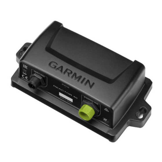
GHP
Installation Instructions
Important Safety Information
See the Important Safety and Product Information guide in the
product box for product warnings and other important
information.
You are responsible for the safe and prudent operation of your
vessel. The autopilot is a tool that enhances your capability to
operate your boat. It does not relieve you of the responsibility of
safely operating your boat. Avoid navigational hazards and
never leave the helm unattended.
Always be prepared to promptly regain manual control of your
boat.
Learn to operate the autopilot on calm and hazard-free open
water.
Use caution when operating the autopilot near hazards in the
water, such as docks, pilings, and other boats.
When in use, beware of hot motor and solenoid components
and the risk of entrapment from moving parts.
Failure to install and maintain this equipment in accordance with
these instructions could result in damage or injury.
NOTICE
To avoid damage to your boat, the autopilot system should be
installed by a qualified marine installer. Specific knowledge of
hydraulic steering componentry and marine electrical systems is
required for proper installation.
Installation Preparation
The autopilot system consists of multiple components. You
should familiarize yourself with all of the component mounting
and connection considerations before beginning installation. You
must know how the components operate together in order to
correctly plan the installation on your boat.
You can consult the layout diagrams
to help understand the mounting and connection considerations.
You should lay out all of the components on the boat as you
plan the installation to make sure your cables will reach each
component. If needed, extension cables (sold separately) for
various components are available from your Garmin
from www.garmin.com.
You should record the serial number of each component for
registration and warranty purposes.
December 2014
Reactor
™
Mechanical
WARNING
CAUTION
(Power and Data
Layout)
dealer or
®
Tools Needed
• Safety glasses
• Drill and drill bits
• 90 mm (3.5 in.) hole saw or a rotary cutting tool
• Wire cutters/strippers
• Phillips and flat screwdrivers
• Cable ties
• Waterproof wire connectors (wire nuts) or heat-shrink tubing
and a heat gun
• Marine sealant
• Portable or handheld compass (to test for magnetic
interference)
• Anti-seize lubricant (optional)
NOTE: Mounting screws are provided for the main components
of the autopilot system. If the provided screws are not
appropriate for the mounting surface, you must provide the
correct types of screws.
Mounting and Connection Considerations
The autopilot components connect to each other and to power
using the included cables. Ensure that the correct cables reach
each component and that each component is in an acceptable
location before mounting or wiring any components.
Helm Control Mounting Considerations
This device should be mounted in a location that is not exposed
to extreme temperatures or conditions. The temperature range
for this device is listed in the product specifications. Extended
exposure to temperatures exceeding the specified temperature
range, in storage or operating conditions, may cause device
failure. Extreme-temperature-induced damage and related
consequences are not covered by the warranty.
The mounting surface must be flat to avoid damaging the device
when it is mounted.
Using the included hardware and template, you can flush mount
the device in the dashboard. If you want to mount the device
using an alternative method where it appears flat with the front
of the dashboard, you must purchase a flat-mount kit
(professional installation recommended) from your Garmin
dealer.
When selecting a mounting location, observe these
considerations.
• The mounting location should be at or below eye level to
provide optimal viewing as you operate your vessel.
• The mounting location should allow easy access to the keys
on the device.
• The mounting surface must be strong enough to support the
weight of the device and protect it from excessive vibration or
shock.
• To avoid interference with a magnetic compass, the device
should not be installed closer to a compass than the
compass-safe distance value listed in the product
specifications.
• The area behind the mounting surface must allow room for
the routing and connection of the cables.
Helm Control Connection Considerations
• The helm control must connect to the NMEA 2000
• Optional NMEA
0183 devices, such as wind sensors, water-
®
speed sensors, or GPS devices can be connected to the
helm control using a data cable
Considerations).
Printed in Taiwan
NOTICE
network.
®
(NMEA 0183 Connection
190-01769-02_0A
Advertisement
Table of Contents

Related Manuals for Garmin GHP Reactor Mechanical


Summary of Contents for Garmin GHP Reactor Mechanical
- Page 1 If needed, extension cables (sold separately) for • Optional NMEA 0183 devices, such as wind sensors, water- ® various components are available from your Garmin dealer or ® speed sensors, or GPS devices can be connected to the from www.garmin.com.
- Page 2 ◦ The solenoid power cable cannot be extended. your boat, you can avoid the step of defining north in the • If you are connecting to a drive unit not sold by Garmin, you setup procedure by meeting all of the following...
-
Page 3: Component Layout
The CCU must be located away from sources of the drive unit. magnetic interference. If you purchased a drive unit from Garmin, it will Drive unit The drive unit power cable cannot be cut or come with the power and feedback cables extended. -
Page 4: Helm Control Installation
Stainless-steel screws may bind when screwed into fiberglass Use the included screws to attach the CCU to the mounting and overtightened. Garmin recommends applying an anti-seize surface. lubricant to the screws before installing them. -
Page 5: Drive Unit Installation
The drive unit (sold separately) must be connected to your rudder control so the GHP Reactor Mechanical autopilot can steer your boat. When you purchase a drive unit sold by Garmin, it will include the correct cables, connectors, and instructions. -
Page 6: Connecting The Ccu
NMEA 2000 and the Autopilot Components feedback sensor is not required. If you are connecting the autopilot to a drive unit not sold by Garmin, you must also install NOTICE a rudder feedback sensor, such as the GRF 10 (sold If you have an existing NMEA 2000 network on your boat, it separately). -
Page 7: Configuring The Autopilot
Select the vessel type. Select the drive unit class (Selecting the Drive Unit Class). If you have a drive unit not sold by Garmin, select the drive- unit voltage and the drive-unit-clutch voltage (Selecting the Drive-Unit Voltage and Drive-Unit-Clutch Voltage). - Page 8 (Calibrating the Rudder). Without touching the rudder or helm control, allow the autopilot to calibrate the rudder. If you have a drive unit not sold by Garmin, tune the drive unit Select an option: (Tuning an Existing Drive Unit). Test the steering direction (Testing the Steering Direction).
- Page 9 With the engine (or engines) running, compare the RPM • If you are performing this procedure outside of the Sea readings on the helm control with the tachometer (or Trial Wizard, from the heading screen, select Menu > tachometers) on the dashboard of your boat. Setup >...
- Page 10 the initial Autotune speed and select Alternate Autotune Testing and Adjusting the Configuration to begin an alternate procedure. NOTICE When the Autotune procedure is complete, gain values are Test the autopilot at a slow speed. After the autopilot has been displayed.
-
Page 11: Advanced Configuration
Enable Dealer Mode (Enabling Dealer Configuration). For almost every installation of a drive unit not sold by Garmin, the generic tuning procedure performed during the Dockside From the heading screen, select Menu > Setup > Dealer Wizard is sufficient to calibrate the drive unit for use with the Autopilot Configuration >... -
Page 12: Nmea 0183 Connection Diagrams
harder and may drain your battery at a faster-than-normal speed. If you set the error tolerance too high, the drive unit will not react until your course is off a significant distance. This causes a less reliable heading hold, and can result in unnecessarily large course corrections. -
Page 13: Specifications
NMEA 2000 LEN 4 (200 mA) *The device withstands incidental exposure to water of up to 1 m for up to 30 min. For more information, go to www.garmin.com/waterrating. NMEA 2000network (provides power to the helm control) 12 Vdc power source... -
Page 14: Nmea 0183 Information
6 (300 mA at 9 Vdc) 129284 Navigation Data *The device withstands incidental exposure to water of up to 1 m for up to 30 min. For more information, go to www.garmin.com/waterrating. 129285 Navigation - Route/WP information 130306 Wind Data... - Page 15 Planing Speed: Allows you to adjust the planing speed of your Error Message Cause Autopilot Action boat. If the value does not match the value on the helm Lost Wind Data The autopilot is no longer • Alarm sounds for control, you can adjust the value.
-
Page 16: Registering Your Device
• In the UK, call 0808 2380000. • In Europe, call +44 (0) 870.8501241. Garmin ® and the Garmin logo are trademarks of Garmin Ltd. or its subsidiaries, registered in the USA and other countries. GHP ™ , GHC ™...
Need help?
Do you have a question about the GHP Reactor Mechanical and is the answer not in the manual?
Questions and answers