Table of Contents
Advertisement
GHP
12 Installation Instructions
™
This revision was written to software version 2.2 of the GHP 12, which
added solenoid drive unit compatibility.
To obtain the best possible performance and to avoid damage to your
boat, install the Garmin
GHP 12 marine autopilot system according
®
to the following instructions. Professional installation of the autopilot
system is highly recommended. Specific training in steering systems
and in marine electrical connections is required to properly install the
autopilot system.
Read all installation instructions before proceeding with the
installation. If you experience difficulty during the installation, contact
Garmin Product Support.
NOTE: There is an installation checklist on the last page of these
instructions. Remove the last page and refer to the checklist as you
proceed through the GHP 12 installation.
Registering the Device
• Go to http://my.garmin.com.
• Keep the original sales receipt, or a photocopy, in a safe place.
For future reference, write the serial number assigned to each
component of your GHP 12 system in the spaces provided on
The serial numbers are located on a sticker on each component.
Contacting Garmin Product Support
• Go to
www.garmin.com/support
country support information.
• In the USA, call (913) 397.8200 or (800) 800.1020.
• In the UK, call 0808 2380000.
• In Europe, call +44 (0) 870.8501241.
July 2011
page
and click Contact Support for in-
190-01289-02 Rev. B
Important Safety Information
You are responsible for the safe and prudent operation of your
vessel. The GHP 12 is a tool that will enhance your capability to operate
your boat. It does not relieve you from the responsibility of safely
operating your boat. Avoid navigational hazards and never leave the
helm unattended.
Always be prepared to promptly regain manual control of your boat.
Learn to operate the GHP 12 on calm and hazard-free open water.
Use caution when operating the GHP 12 near hazards in the water, such
as docks, pilings, and other boats.
See the Important Safety and Product Information guide in the product
box for product warnings and other important information.
Equipment to be connected to this product should have a fire enclosure
or be provided with a fire enclosure.
Always wear safety goggles, ear protection, and a dust mask when
drilling, cutting, or sanding.
When drilling or cutting, always check the opposite side of the surface.
Be aware of fuel tanks, electrical cables, and hydraulic hoses.
3.
WaRnInGS
CautIon
Notice
Printed in Taiwan
Advertisement
Table of Contents

Related Manuals for Garmin GHP 12 Autopilot System


Summary of Contents for Garmin GHP 12 Autopilot System
-
Page 1: Ghp ™ 12 Installation Instructions
This revision was written to software version 2.2 of the GHP 12, which added solenoid drive unit compatibility. To obtain the best possible performance and to avoid damage to your boat, install the Garmin GHP 12 marine autopilot system according ®... -
Page 2: Table Of Contents
Enabling Dealer Autopilot Configuration ... Advanced Configuration Settings ... Manually Running the Automated Configuration Procedures ... Manually Defining Individual Configuration Settings ... Manually Adjusting the Settings for a Non-Garmin Drive Unit ... Performing Advanced Tuning Procedures for Non-Garmin Drive Units ... appendix ...21 NMEA 0183 Wiring Diagrams ... -
Page 3: Ghp 12 Package Contents And Tools Needed
(optional) Shadow Drive, are included in the GHP 12 core box. The drive unit is sold separately are missing, contact your Garmin dealer immediately. Record the serial number of each component in the space provided. -
Page 4: Alarm
CCu/ECu Interconnect Extension Cables When installing the GHP 12 system, you may need to mount the CCU farther than 16 ft. (5 m) from the ECU. Garmin offers optional replacement or extension cables for purchase if this is necessary. type Length Replacement 32 ft. (10 m) Replacement 66 ft. -
Page 5: Installation Preparation
• The cables connected to the drive unit cannot be extended. • If you using a non-Garmin drive unit, a GHP 12 drive unit power cable (sold separately), and a GHP 12 rudder feedback cable (sold separately) must be used to adapt your drive unit for use with the... -
Page 6: Shadow Drive Mounting Considerations
Shadow Drive Mounting Considerations • Mount the Shadow Drive horizontally and as level as possible, using cable ties to firmly secure it in place. • Mount the Shadow Drive at least 12 in. (0.3 m) away from magnetic material, such as speakers and electric motors. •... -
Page 7: General Connections Diagram
The drive unit must be installed by an experienced professional the drive unit power cable cannot be cut or extended. If you are using the GHP 12 with a non-Garmin drive unit, you must purchase a GHP 12 drive unit power cable and a GHP 12 rudder feedback cable Mount the CCU with the cables pointing straight down The ECU can be mounted in any orientation. -
Page 8: General Component Layout Diagram
The CCU must be installed in the front half of the boat, Do not cut or extend the drive unit cables. If you are using the GHP 12 with a non-Garmin drive unit, you must purchase a GHP 12 drive unit cable (page The ECU can either be connected to a 12 or a 24 Vdc battery. -
Page 9: Installation Procedures
Preparing a non-Garmin Drive unit In order to use a non-garmin drive unit with the GHP 12, you must install both the GHP 12 drive unit power cable and the GHP 12 rudder feedback cable. Both cables are sold separately. -
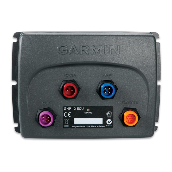
Page 10: Ecu Installation
4. Connect the GHP 12 rudder feedback cable (not included) to your drive unit, based on the wire colors and functions defined below. Wire Color Function Feedback positive (+) Black Feedback negative (-) Yellow Feedback wiper If necessary, extend the appropriate wire with 22 AWG (.33 mm wire. -
Page 11: Connecting The Ccu
Stainless-steel screws may bind when screwed into fiberglass and overtightened. Garmin recommends applying an anti-galling, stainless anti-seize lubricant to the screws before installing them. Before you can mount the GHC 10, you must select a mounting location (page 1. -
Page 12: Connecting The Ghc 10
GPS device, to your NMEA 2000 network to use the advanced features of the GHP 12. For more information on NMEA 2000, go to www.garmin.com. Connecting the GHC 10 to an Existing nMEa 2000 network 1. Determine where to connect the GHC 10 ➊ to your existing NMEA 2000 backbone ➋. -
Page 13: Building A Basic Nmea 2000 Network For The Ghc 10 And The Ccu
Connecting the CCu to an Existing nMEa 2000 network 1. Determine where to connect the CCU ➊ to your existing NMEA 2000 backbone ➋. ➍ ➌ ➋ 2. Disconnect one side of a NMEA 2000 T-connector from the network. 3. If necessary, to extend the NMEA 2000 network backbone, connect a NMEA 2000 backbone extension cable (not included) to the side of the disconnected T-connector. -
Page 14: Connecting Optional Devices To The Ghp 12 Autopilot System
Connecting optional Devices to the GHP 12 autopilot System To use advanced features of the GHP 12, optional NMEA 2000-compatible or NMEA 0183-compatible devices, such as a wind sensor, a water-speed sensor, or a GPS device, can be connected to the NMEA 2000 network or to the GHC 10 through NMEA 0183. Connecting an optional nMEa 2000-compatible Device to ... -
Page 15: Configuring The Ghp 12
4. Select the vessel type. 5. Select the drive unit class (page 15). 6. If you have a non-Garmin drive unit, select the drive unit voltage (page 15). 7. If you have a non-Garmin drive unit, select the clutch voltage (page 15). -
Page 16: Tuning A Non-Garmin Drive Unit
NOTE: This does not apply to a solenoid drive unit. If you installed a non-Garmin drive unit, you must calibrate the drive unit for use with the GHP 12. 1. Center the rudder position, let go, and select Continue. -
Page 17: Sea Trial Wizard
Sea trial Wizard The sea trial wizard configures the fundamental sensors on the autopilot, and it is extremely important to complete the wizard in conditions appropriate for your boat. You must perform the sea trial wizard while under motor, and not while under sail. -
Page 18: Setting North
4. If autotune fails again, repeat steps 1–3 until the autotune completes successfully. 5. If the autotune procedure continues to fail after you reach maximum cruising speed, reduce your speed to the initial autotune speed and select Alternate Autotune to begin an alternate autotuning procedure. -
Page 19: Reducing The Risk Of Ecu Drive Circuit Overload
• If you have a powerboat, select an option: ◦ Select Low Speed or High Speed and use the arrows on the GHC 10 to adjust how tightly the rudder holds the heading and makes turns at low speed or high speed. If you set this value too high, the autopilot may be overactive, attempting to constantly adjust the heading at the slightest deviation. -
Page 20: Manually Adjusting The Settings For A Non-Garmin Drive Unit
Notice Providing an incorrect drive-unit-voltage, clutch-voltage, or max- current value for your non-Garmin drive unit can damage your drive unit. NOTE: If you adjust any of these values or run any of these tuning procedures, you must re-run the autotune procedure 1. -
Page 21: Appendix
6. When the drive-unit speed is tuned correctly, select Done. tuning the Error tolerance on a non-Garmin Drive-unit The error tolerance of the drive unit determines how much error the autopilot allows before adjusting the drive unit. If you set the error tolerance too low, the drive unit will react to the slightest course deviation. - Page 22 Example two of three - only one Receiving Wire If your NMEA 0183-compatible device has only one receiving wire (Rx), connect it to the blue wire (Tx/A) from the GHC 10, and leave the white wire (Tx/B) from the GHC 10 unconnected. ➋ ➌ ➊ ➌ > ➍ ➎...
-
Page 23: Specifications
Specifications Device Specification Measurement Dimensions (W×H×D) 6 (167.6 × 116.8 × 50.8 mm) Weight 1.5 lb. (0.68 kg) Temperature from 5°F to 140°F (from -15°C to 60°C) range Case material Fully gasketed, high-impact aluminum alloy, waterproof to IEC 529 IPX7 standards Power cable 9 ft. -
Page 24: Nmea 0183 Information
type Description Transmit 059392 ISO Acknowledgment 059904 ISO Request 060928 ISO Address Claim 126208 NMEA - Command/Request/Acknowledge Group Function 126464 Transmit/Receive PGN List Group Function 126996 Product Information 128259 Water Speed 129025 Position - Rapid Update 129026 COG & SOG - Rapid Update 129283 Cross Track Error 129284... -
Page 25: Ghp 12 Configuration Settings
GHP 12 Configuration Settings Although all of the configuration is typically completed automatically through wizards, you can manually adjust any setting NOTE: Depending upon the configuration of the autopilot, certain settings may not appear. NOTE: On a powerboat, each time you change to the Speed Source setting, you must review the Verify Tachometer, Low RPM Limit, High RPM Limit, Planing RPM, Planing Speed, or Max Speed settings, where applicable, prior to performing the autotune procedure Category Setting... - Page 26 Allows you to specify the class of your drive unit (refer to information). Select Other for non-Garmin drive units. Only applicable if the Drive Unit Class has been set to “Other” or “Solenoid”. This setting tells the autopilot the voltage it should supply to the drive unit motor. Refer to the documentation supplied by the manufacturer of your drive unit to determine motor voltage specification.
-
Page 27: Error And Warning Messages
Category Setting Steering System Setup > Clutch Voltage Drive Unit Class > Other Steering System Setup > Generic Drive Unit Drive Unit Class > Other Tune Steering System Setup > Speed Tune Drive Unit Class > Other > Advanced Drive Unit Tuning Steering System Setup >... - Page 28 Error Message Cause Drive unit overload The average drive unit current value goes above a specified threshold. • Class A: 8 amps • Class B: 16 amps • Other: user specified Rudder sensor is not The drive unit rudder sensor has not been calibrated. calibrated.
-
Page 29: Mounting Templates
Mounting templates Use the following mounting templates during the mounting process. ECu Mounting template CCu Mounting template Up, when installing on a ➊ vertical surface GHP 12 Installation Instructions ➊... - Page 30 This page is intentionally left blank. GHP 12 Installation Instructions...
-
Page 31: Ghp 12 Installation Checklist
GHP 12 Installation Checklist Detach this checklist from the installation instructions and use it during the GHP 12 installation process. Read all installation instructions before installing the GHP 12. Contact Garmin Product Support if you have any questions during the installation process. Refer to the diagram on... - Page 32 All rights reserved. Except as expressly provided herein, no part of this manual may be reproduced, copied, transmitted, disseminated, downloaded or stored in any storage medium, for any purpose without the express prior written consent of Garmin. Garmin hereby grants permission to download a single copy of this manual onto a hard drive or other electronic storage medium to be viewed and to print one copy of this manual or of any revision hereto, provided that such electronic or printed copy of this manual must contain the complete text of this copyright notice and provided further that any unauthorized commercial distribution of this manual or any revision hereto is strictly prohibited.
Need help?
Do you have a question about the GHP 12 Autopilot System and is the answer not in the manual?
Questions and answers
the screen reports searching for autopilot what does that mean
When the Garmin GHP 12 Autopilot System screen reports "searching for autopilot," it means the GHC (control head) has lost connection with the CCU (Course Computer Unit) and is attempting to re-establish communication.
This answer is automatically generated