MINN KOTA RAPTOR Owner's Manual
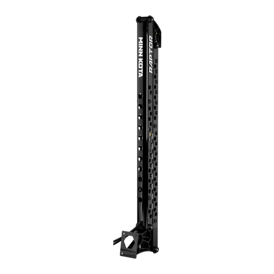
Shallow water anchor
Hide thumbs
Also See for RAPTOR:
- Installation instructions manual (96 pages) ,
- Installation instructions manual (108 pages)
Table of Contents
Advertisement
Advertisement
Table of Contents

Related Manuals for MINN KOTA RAPTOR


Summary of Contents for MINN KOTA RAPTOR
- Page 1 RAPTOR SHALLOW WATER ANCHOR Owner's Manual...
- Page 2 NOTICE: Do not return your Minn Kota product to your retailer. Your retailer is not authorized to repair or replace this unit. You may obtain service by: calling Minn Kota at (800) 227-6433; returning your Raptor to the Minn Kota Factory Service Center;...
- Page 3 HYDRAULIC DIAGRAM ..................... 33 COMPLETING THE INSTALLATION ..................34 USING THE RAPTOR ......................39 Controlling the Raptor with the Indicator Panel ............41 Controlling the Raptor with the Remote ..............44 PAIRING THE RAPTOR ..................... 49 THE RAPTOR APP ......................54 SERVICE &...
- Page 4 WARNING The Raptor should be disconnected from the power source when it is not in use or is off the water for more than a month. When connecting the power-supply cables of the Raptor to the battery or power switch, ensure that they are not kinked or subject to chafe and route them in such a way that persons cannot trip over them.
- Page 5 Such repair or replacement shall be the sole and exclusive liability of Johnson Outdoors Marine Electronics, Inc. and the sole and exclusive remedy of the purchaser for breach of this warranty. The Raptor spike is covered by the five year warranty (plus parts and labor to install).
- Page 6 KNOW YOUR BOAT Port Starboard Inboard Outboard Keel Port Starboard Gunwale Transom Stern Gunwale Stern Hull 6 | minnkotamotors.com ©2020 Johnson Outdoors Marine Electronics, Inc.
- Page 7 Mode Speed Button Button/ Anchor Auto Selection DOWN Button Button Spike NOTICE: Specifications subject to change without notice. This diagram is for reference only and may differ from your actual Raptor. minnkotamotors.com | 7 ©2020 Johnson Outdoors Marine Electronics, Inc.
- Page 8 INSTALLING THE RAPTOR Your new Raptor comes out of the box with the hardware you’ll need to install it directly to the transom of your boat. If you have an irregularly shaped transom that cannot accept a direct mount, or you prefer to mount the Raptor with an adapter bracket for ease of mounting and removal, please visit minnkotamotors.com...
- Page 9 Not following proper installation and rigging instructions may result in injury. Mounting the Raptor too low can cause undue drag from the Raptor or Mounting Bracket when operating the boat. It is important to mount the Raptor as recommended to avoid unsafe driving conditions.
- Page 10 If these conditions are not met, please consider using an optional Minn Kota adapter bracket accessory. There are many adapter brackets designed for the Raptor that allow for greater adjustability of the mount and allow for greater clearances to operate the Raptor. Please visit minnkotamotors.com...
- Page 11 INSTALLING THE RAPTOR Hydraulic Pump Mounting Considerations Minn Kota recommends reviewing all mounting considerations for the hydraulic pump and hose routing for the Raptor to ensure that all circumstances are taken into account before installation. In order to successfully route the hydraulic hoses and mount the hydraulic pump, please consider the following: 1.
- Page 12 INSTALLING THE RAPTOR 4. Hydraulic Fluid and Filling Access - Make sure that the mounting location allows for the pump to be filled with hydraulic fluid. The cap to the pump assembly must be accessible to fill the hydraulic pump reservoir with hydraulic fluid. Be sure that the installation location allows access with a funnel or similar tool to aide in filling the reservoir.
- Page 13 INSTALLING THE RAPTOR 6. Power Source - Make sure that the power cord can reach its Hydraulic Hydraulic Hydraulic Hoses intended power source and will not pose as a tripping hazard. It Hoses Hoses is recommended to mount the pump as close to the power source...
- Page 14 Edges NOTICE: The Raptor weighs approximately 27lbs. It is recommended to have a second person help with installation. With the Raptor set aside, take the Mounting Marked Locations Marked Locations Template (Item #34) and place it along the marked Marked Marked edges.
- Page 15 Marine Grade Sealant CAUTION Hydraulic Hoses Hydraulic Hoses Do not use the Built-in Mounting Bracket or Raptor as a step to enter the boat. The bracket will be slippery when wet and is not designed to support people. Using this Drilled Location Drilled Location product as a step may result in injury.
- Page 16 Applying an anti-seize may help prevent seizing. Fender Flange Washer NOTICE: If you are replacing a Talon with the Raptor, DO NOT REUSE the 5/16" Talon mounting hardware for mounting purposes. Built-in Mounting Bracket Built-in Mounting Bracket Transom 16 | minnkotamotors.com...
- Page 17 INSTALLING THE RAPTOR Rotating the Pump Reservoir After reviewing the mounting considerations for your installation, you may have identified that the reservoir on your Pump Assembly needs to be rotated. If your installation requires rotating the Pump Reservoir, please follow the instructions below. If your installation does not require the Pump Reservoir to be rotated, please see "Installing the Hydraulic Pump "...
- Page 18 INSTALLING THE RAPTOR With the Pump Reservoir rotated and seated in place, use the 5/16" Deep Well Socket or 5/16" Ratchet- Style Wrench to replace the four Flanged Bolts. Tighten to 12 in-lbs. With the Flanged Bolts back in place, continue with the Hydraulic Pump installation.
- Page 19 INSTALLING THE RAPTOR Installing the Hydraulic Pump Review the mounting considerations at the beginning of the NOTICE: Installation for your Pump Assembly may installation. If it is necessary to rotate the Pump Assembly, refer to vary from the standard installation. Review the mounting the "Rotate the Pump Assembly"...
- Page 20 INSTALLING THE RAPTOR ITEM(S) NEEDED #16 X 2 #12 X 2 The U-shaped Slots on the Mounting Bracket allow Belleville Belleville for adjustability between the Pump and the mounting Washers Washers bracket. Take both Hex Head Cap Screws (Item #16) and place one 3/8"...
- Page 21 INSTALLING THE RAPTOR ITEM(S) NEEDED #14 X 2 #18 X 2 Replace the Pump Bracket only and align the Stainless Stainless Pump Bracket Pump Bracket Mounting Holes with the Pilot Holes. Steel Screw Steel Screw Serrated Serrated Take two 1" Stainless Steel Screws (Item #18) and...
- Page 22 INSTALLING THE RAPTOR With the Two-Piece Mounting Bracket fully installed, replace the Pump Assembly on the Mounting Bracket. Pump Assembly Pump Assembly Make sure that the Belleville Washers sit between the head of the screw and the Mounting Bracket. The...
- Page 23 DOWN/deploy function. The hose with the black cap (DOWN) extends further from the Raptor due to its mounting position within the Raptor. Determine if hydraulic hoses may be routed through an established route on the boat to the Hydraulic Pump. The Hydraulic Hoses are 15 feet in length.
- Page 24 INSTALLING THE RAPTOR Locate the Hydraulic Hoses that exit the Raptor, and note the Grommet on each hose. If the Caps Caps Hydraulic Hoses are tie wrapped in a circle, it may be necessary to carefully cut the tie wrap with a scissors or similar cutting tool and unwrap the hoses.
- Page 25 INSTALLING THE RAPTOR Take the Hydraulic Hoses with the green and black 3/4" Drilled Hole 3/4" Drilled Hole Caps still in place and insert one hose into each drilled for Hose Routing for Hose Routing Hydraulic hole. If necessary, slide the Grommets back so that the...
- Page 26 Circuit may include adjustments to the Hydraulic Hoses, or adjustments to the bypass valves. Changes to pressure in the Hydraulic Circuit may cause the Raptor to fall and pose a striking hazard due to gravity. Rest the Spike on the ground to avoid this hazard.
- Page 27 Remove the black Cap on the Hydraulic Hose and the black Cap on the "DN" Hydraulic Fitting. The Hydraulic Hose with the black Cap will be the longer of the two hoses that come from the Raptor. Under the Black Caps black Cap on the "DN"...
- Page 28 Installing the Remote Bracket The Raptor comes with two remotes. Mounting the Remote Bracket to your boat is an option installation. The Remote Bracket is only intended to hold one remote. Mounting the Remote Bracket in the boat is based on personal preference. It is recommended to mount the Remote Bracket to a flat surface where the remote can be easily accessed for anchor control.
- Page 29 Altering boat wiring should be completed by a qualified marine technician. The following specifications are for general guidelines only. CAUTION Please read the following information before connecting your Raptor(s) to your battery in order to avoid damaging your product and/or voiding your warranty. CAUTION These guidelines apply to general rigging to support your Minn Kota product.
- Page 30 For more information on battery selection and rigging, please visit minnkotamotors.com. The Raptor draws a small amount of residual current from the battery even when not in use. If the Raptor will not be used for more than a month, the Raptor power leads should be disconnected from the battery.
- Page 31 WARNING • The Raptor draws a small amount of residual current from the battery even when not in use. If the Raptor is not be used for more than a month, or while the battery/batteries are being charged, the Raptor power leads should be disconnected from the battery. It is recommended the Raptor be connected to the Starting Battery through a battery selector or power disconnect switch.
- Page 32 WIRING DIAGRAM RAPTOR The following wiring diagram applies to the Raptor. The Pressure Transducer is included in Active Anchoring Models only. Pressure Transducer (AA Models only) B- M- Battery (+) White Motor (+) red Battery (-) black Motor (-) black...
- Page 33 HYDRAULIC DIAGRAM RAPTOR The following hydraulic diagram applies to all Raptors. DOWN/ retract deploy Down Down minnkotamotors.com | 33 ©2020 Johnson Outdoors Marine Electronics, Inc.
- Page 34 Bluetooth connection between the remotes that come paired with the anchor from the factory and the Pump Assembly. Before using the Raptor for its intended purpose, confirm that the installation of the components is complete and then finalize the installation for successful operation.
- Page 35 Place a clean Funnel or similar tool onto the Reservoir. Notice the maximum and minimum fill Funnel lines on the Reservoir. The Raptor Pump Reservoir is designed to hold 1 quart of Hydraulic Fluid. Take Maximum Fluid Absorbent Insert...
- Page 36 Raptor Spike too closely while operating, neither with UP/retract body parts nor with objects. The Raptor is powerful and may endanger or injure you or others. While the Raptor is operating, watch out for persons and obstructions while controlling the Raptor.
- Page 37 COMPLETING THE INSTALLATION Before normal use of the Raptor, trailer the boat to a body of water. Unload the boat into the water and drive it to water that is no less than the depth of your anchor or a minimum of 10 feet. It is recommended...
- Page 38 WARNING • Periodically inspect hoses for signs of wear or damage. Operation of the Raptor system with a worn or damaged hydraulic hose may cause damage, unexpected operation or injury. • In the event a hydraulic hose ruptures, bursts or becomes disconnected during operation, immediately shut off power at the pump assembly and manually relieve pressure in the hydraulic system using the manual bypass valves.
- Page 39 USING THE RAPTOR RAPTOR FEATURES Become familiar with the features of the Raptor to maximize the capabilities this product offers. Auto Drive In select Modes, Auto-Drive will automatically power the Spike into the bottom with two successive hits. Raptor actually drives the anchor in for you to ensure the anchor is seated.
- Page 40 Raptor when it deploys. Modes are identified on the Indicator Panel and the Raptor remotes. Raptor is capable of anchoring in most conditions and it is important to select the right anchoring mode.
- Page 41 USING THE RAPTOR CONTROLLING THE RAPTOR WITH THE INDICATOR PANEL PAIR/Maintenance Button Button Mode Pair/Maintenance DOWN Button Pair/Maintenance LED Press and hold to retract the anchor. The anchor will While the anchor is in PAIR Mode, the Pair/ continue to retract when the button is held until the Maintenance LED will flash blue.
- Page 42 CAUTION The spaces between the Outer Arm, Inner Arm, Spike and brackets of the Raptor can create a pinch point. Do not come in contact with an area of the Raptor that may cause a pinch point while it is moving in any direction to avoid the risk.
- Page 43 CAUTION The spaces between the Outer Arm, Inner Arm, Spike and brackets of the Raptor can create a pinch point. Do not come in contact with an area of the Raptor that may cause a pinch point while it is moving in any direction to avoid the risk.
- Page 44 It is not recommended to leave the boat while Raptor from the factory are pre-paired. If the network operating the Raptor with the remote. Doing so is at the owner's connection between the remotes and the anchor is risk. This product does not relieve you from the responsibility of interrupted, please see the "Pairing the Raptor"...
- Page 45 CAUTION The spaces between the Outer Arm, Inner Arm, Spike and brackets of the Raptor can create a pinch point. Do not come in contact with an area of the Raptor that may cause a pinch point while it is moving in any direction to avoid the risk.
- Page 46 CAUTION The spaces between the Outer Arm, Inner Arm, Spike and brackets of the Raptor can create a pinch point. Do not come in contact with an area of the Raptor that may cause a pinch point while it is moving in any direction to avoid the risk.
- Page 47 Modes. Toggle Active Anchoring Active Anchoring is a feature that comes pre-installed on select Raptor models. To learn more about Active Anchoring, see the "Using the Raptor" section of these instructions. Active Anchoring is engaged and disengaged by a...
- Page 48 Raptor that the remote is controlling, when two Raptors are installed on the boat. The selection toggles between a Raptor mounted on the Port or Starboard side of the boat, or it can control both Raptors at the same time.
- Page 49 PAIRING A REMOTE TO A SINGLE RAPTOR Every Raptor comes direct from the factory with 2 remotes already paired to the Raptor. If more remotes are paired to the Raptor than the network allows, the Raptor will pair the new remote and remove the remote that was least recently used from the network.
- Page 50 For more information on Pairing and controlling your Raptor(s) from a Humminbird, please see the Owner's Manual for your Humminbird. For more information on how to Pair and control a Raptor on an i-Pilot or i-Pilot Link, please see the corresponding Owner's Manual. 50 | minnkotamotors.com...
- Page 51 Raptor is installed on. Once complete, the Raptor remotes will need to be re-paired to the dual Raptor system. Please see the "Pairing a Remote to Two Raptors" section of this manual to pair a remote.
- Page 52 Mounting Location" section of this manual. If the two Raptors are already paired together, a remote can be paired to the dual Raptors. Either Raptor in the network can be used to Pair a remote to the dual Raptor. If more remotes are paired to the dual Raptors than the network allows, the Raptor will pair the new remote and remove the remote that was least recently used from the network.
- Page 53 The Raptor memory is now clear of all previously paired devices. CLEARING A PAIRED RAPTOR FROM THE REMOTE The Remote was designed so that a paired Raptor can be cleared from memory. Press and hold the Up button and the Down...
- Page 54 THE RAPTOR APP Raptor App Home Screen Raptor App Minn Kota offers a Raptor app that can be used to control and Icon on Device update the Raptor using a Bluetooth enabled device. The Raptor ® app is available for download on iOS devices through the Apple...
- Page 55 The Raptor Selection options are only visible when activated. when the Raptor App is set up to control two Raptors. Raptor Selection - Both Indicates both the Port and Starboard Raptors are selected and will be controlled while operating.
- Page 56 LAUNCHING THE APP & DEMO MODE Launching the app when it is not paired with the Raptor will allow you to try it in Demo Mode. The first time the app is launched, you must agree with the disclaimer in order to continue. Become familiar with the app screens in order to understand how to operate your Raptor with the app.
- Page 57 When a Raptor is paired with a device, the Raptor app on the device records information about the paired Raptor(s), including the software version installed on each. This information can be used to detect if a Raptor requires a software update. To check the software version on paired Raptor(s), follow the steps below.
- Page 58 NOTICE: Your device will only be able to connect to a The Raptor App can be used to control the Raptor using a device Raptor and be paired if the device is Bluetooth enabled. that is paired to the Raptor with a Bluetooth connection. Before pairing the device with the Raptor, the Raptor App should first be successfully downloaded.
- Page 59 Pairing a Device with Two Raptors In order for the Raptor App to pair two Raptors to the device, the Raptors first need to be paired together. To learn how to pair two Raptors together, read the "Pairing Two Raptors and Programming the Mounting Location" section of the Raptor Manual. Once the Raptors are paired together, follow the directions for "Pairing a Device with a Single Raptor".
- Page 60 THE RAPTOR APP Update the Raptor from the Raptor App Raptor software updates are performed through the Raptor app. The Raptor must be paired and communicating with the device through a Bluetooth connection in order for the Raptor to be updated.
- Page 61 Raptor when the Raptor software is updated. When the paired remotes are repaired, the software updates will be pushed to the remote. For details on how to Pair the remote to the Raptor, see the "Pairing the Raptor" section of this manual. minnkotamotors.com | 61...
- Page 62 10. Within the range of options, the lower the number, the lower the speed, the higher the number, the quicker the Raptor will move at the selected speed. Follow the instructions below to adjust the range of the Speed for each option.
- Page 63 Up Sensitivity and when it is deployed is the Down Sensitivity. Sensitivity for both Up and Down range from -10 to 10 with the default being 0. In a Dual Raptor system, the ideal sensitivity may not be the same for both Raptors and should be adjusted independently.
- Page 64 THE RAPTOR APP The Raptor Sensitivity will list a selection for "Up 2c - Single Raptor 2c - Dual Raptor Sensitivity" and "Down Sensitivity". The default or currently selected sensitivity will follow the selection. To change the Sensitivity, select which one you would like changed.
- Page 65 Reverse Raptor Left/Port and Right/Starboard Installation The Reverse L/R Installation selection is only available on the App Menu when a dual Raptor System is set up. This selection is used to reverse the mounting location as recognized in the Raptor system.
- Page 66 CAUTION Before beginning any maintenance work, disconnect the Raptor from the battery or if connected to a battery selector switch or power disconnect switch, make sure that it is turned to the "off" position. Failure to disconnect power during maintenance work may result in shock, unexpected operation and/or injury.
- Page 67 SERVICE & MAINTENANCE Remove the Battery Cover and old battery and Battery replace with a new CR2450 coin cell battery. Note Cover the proper polarity of the battery. Remote NOTICE: Back The replacement battery must be Battery a model CR2450 coin cell type. It is strongly recommended that a high quality battery is used.
- Page 68 Pump. When two Raptors are Paired together, the disabled control is specific to the Hydraulic Pump placed in Maintenance mode. If the second Raptor, in a Paired system is not placed in Maintenance mode, the devices and remotes are still able to control the Raptor not placed in Maintenance Mode.
- Page 69 Inner Arm Inner Arm the Raptor that may cause a pinch point while it is moving in any direction to avoid the risk. Stay clear of the anchor if it is not held in place under the power of the Hydraulic Circuit or physical restraint.
- Page 70 When making changes to the Hydraulic Circuit, it is recommended to secure the Raptor for transport. This includes when taking the Raptor in and out of Maintenance Mode. Securing the Raptor will prevent unexpected deployment that may result from changes to pressure in the Hydraulic Circuit.
- Page 71 Arm, Inner Arm, Spike and brackets of the Raptor can create a pinch point. Do not come in contact with an area of the Raptor that may cause a pinch point while it is moving in any direction to avoid the risk. Stay clear of the anchor if it...
- Page 72 Bypass Valves one turn in a clockwise direction to close the Hydraulic Circuit. Use the Pressure Wrench to hand tighten the Bypass Valves until they are tight. Once the Circuit is closed, the Raptor is held in position from the Hydraulic pressure and should not move freely.
- Page 73 Cover snaps together to provide a watertight seal. Cover Seal CHECKING HYDRAULIC FLUID LEVELS The Raptor Pump Reservoir has a minimum and maximum hydraulic fluid level marked on the side of the Pump Reservoir. Maximum Maximum Fill Line...
- Page 74 The Spike for your Raptor comes with a lifetime guarantee. See the Warranty section of the manual for further details. In order to replace the Spike, you must be able to safely reach the top of the Raptor anchor. It is recommended to place the Raptor in Maintenance...
- Page 75 Replace the Spike and align the holes in the top of Spike the Spike with the Half-moon Grooves on the top of the Spike. The logo on the Spike molding should be facing away from the Raptor. Half-moon Grooves minnkotamotors.com | 75...
- Page 76 SERVICE & MAINTENANCE With the Spike in place, take the two 1/4 - 20 X 1.75 inch Stainless Steel Hex Bolts and replace them on the Upper Knuckle. Be sure to correctly Upper Knuckle capture the Spike as the Bolts pass through the Upper Knuckle, past the Spike grooves and exit the Brass other side of the Upper Knuckle.
- Page 77 • The Raptor remote is powered by a coin cell battery. The battery level is displayed as a simple voltage measurement, converted to a percent of useable life. The reading is updated about once per hour when the Raptor is in use. The voltage of a coin cell battery can vary drastically based on intensity of prior use and ambient temperature.
- Page 78 Authorized Service Centers Minn Kota has over 800 authorized service providers in the United States and Canada where you can purchase parts or get your products repaired. Please visit our Authorized Service Center page on our website to locate a service provider in your area.
- Page 79 Minn Kota Raptors are not subject to the disposal regulations EAG-VO (electric devices directive) that implements the WEEE directive. Nevertheless, never dispose of your Minn Kota Raptor in a garbage bin but at the proper place of collection of your local town council.
- Page 80 ENVIRONMENTAL RATINGS Ambient operating temperature range: -10C to 50C Ambient operating humidity range: 5% to 95% Maximum operating altitude: 10,000 feet RADIO OPERATION TRADEMARKS CONTROLLER Minn Kota , Humminbird , i-Pilot and i-Pilot Link™ are ® ® ®...
- Page 81 12 VOLT - 8'/10' RAPTOR The parts diagram and parts list provide Minn Kota® WEEE compliance disassembly instructions. For more information about where you should dispose of your waste equipment for recycling and recovery and/or your European Union member state requirements, please contact your dealer or distributor from which your product was purchased.
- Page 82 Installation Hardware & Remote Parts List Assembly Part # Description Notes Quantity 2994943 BAG, ASM, RAPTOR HWD 2994944 BAG ASM, RAPTOR PUMP HDW 2994156 TRANSMITTER ASM, RAPTOR 2771829 BRACKET,DASH MNT HLDR/TAPE KIT 2886422 COVER, BATTERY COMPARTMENT ASY Item Part #...
- Page 83 PARTS DIAGRAM & PARTS LIST RAPTOR ANCHOR Raptor 8ft Parts Diagram 74 72 72 74 74 72 72 74 90 94 74 72 72 74 94 90 90 94 minnkotamotors.com | 83 ©2020 Johnson Outdoors Marine Electronics, Inc.
- Page 84 Raptor 8ft Parts List Assembly Part # Description Notes Quantity 2777301 BUSHING KIT, MAIN, RAPTOR *ASSEMBLY S QTY 2* 2777303 BUSHING KIT, CENTER, 8' RAPTOR *8FT* 2772019 SPIKE KIT 8' RAPTOR *8FT* 2777300 UPPER KNUCKLE KIT, RAPTOR 2778411 CYLINDER KIT, RAPTOR 2771400...
- Page 85 PARTS DIAGRAM & PARTS LIST Item 2776515 RAPTOR UPPER ARM, 8', RED Notes Quantity 2350207 CAP-VINYL, .562" X 1/2" BLACK 2350208 CAP-VINYL, .562" X 1/2" GREEN 2355120 BUMPER, SPIKE UPPER 2352300 SUPPORT, CENTER CYLINDER *ASSEMBLY N* 2351926 BRACKET, UPPER KNUCKLE, MACH...
- Page 86 PARTS DIAGRAM & PARTS LIST Raptor 10ft Parts Diagram 144 142 144 144 144 142 BB CC 160 164 160 164 164 160 160 164 86 | minnkotamotors.com ©2020 Johnson Outdoors Marine Electronics, Inc.
- Page 87 2772020 SPIKE KIT 10' RAPTOR *10FT* 2777300 UPPER KNUCKLE KIT, RAPTOR 2778411 CYLINDER KIT, RAPTOR 2771400 HYDRAULIC HOSE REP KIT, RAPTOR 2771401 HYDRAULIC HOSE EXT KIT, RAPTOR *NOT INCLUDED FROM THE FACTORY* 2776532 RAPTOR UPPER ARM, 10', SILVER *10FT* 2776533...
- Page 88 BOLT-1/4-20 X 1.75 HEX SS *ASSEMBLY S* *ASSEMBLY R* 2353110 NUT-1/4-20 BRASS NYLON INSERT *ASSEMBLY S* *ASSEMBLY R* 2355642 DECAL, MINN KOTA RAPTOR BLK *WHITE* *AA* *ASSEMBLY BB* *ASSEMBLY AA* *BLACK* *RED* *SILVER* *ASSEMBLY DD* 2355640 DECAL, MINN KOTA RAPTOR WHT *ASSEMBLY CC*...
- Page 89 PARTS DIAGRAM & PARTS LIST RAPTOR HYDRAULIC PUMP Raptor Hydraulic Pump Parts Diagram minnkotamotors.com | 89 ©2020 Johnson Outdoors Marine Electronics, Inc.
- Page 90 MOTOR ASSEMBLY, RAPTOR 2778210 PRESSURE TRANSDUCER ASM,RAPTOR 2774046 RAPTOR CTRL BOARD ASM *8FT* 2774043 RAPTOR W/AA CTRL BRD ASM 8' *8FT AA* 2774044 RAPTOR W/AA CTRL BRD ASM 10' *10FT AA* 2776720 CAP AND PLUG KIT, RAPTOR *NOT INCLUDED FROM THE FACTORY*...
- Page 91 2354041 PCB ASM, RAPTOR *ASSEMBLY LL* *ASSEMBLY D* *AA* *ASSEMBLY F* *ASSEMBLY E* *ASSEMBLY MM* 2354040 PCB ASM, RAPTOR W/AA *ASSEMBLY NN* *ASSEMBLY MM QTY 4* * ASSEMBLY NN QTY 4* *ASSEMBLY 2305404 SHRINK TUBE-.374 ID X 1.0" LL QTY 4* *ASSEMBLY FF QTY 2* *ASSEMBLY D*...
- Page 92 1810258 RAPTOR MOUNTING ADAPTER BRACKETS Raptor mounting brackets come in a variety of configurations to meet your mounting needs. They feature a light weight, aluminum construction for superior strength. Constructed with a powder coated exterior for corrosion resistance and include stainless steel mounting hardware.
Need help?
Do you have a question about the RAPTOR and is the answer not in the manual?
Questions and answers