
Related Manuals for Advantech ASMB-805 Series


Summary of Contents for Advantech ASMB-805 Series
- Page 1 User Manual ASMB-805 Series ASMB-805 LGA 2066 Intel xeon® W Workstation with 8 DDR4, 3 PCIe x16, 6 SATA3, 8 USB3.0, IPMI...
- Page 2 No part of this manual may be reproduced, copied, translated or transmitted in any form or by any means without the prior written permission of Advantech Co., Ltd. Information provided in this manual is intended to be accurate and reliable. How- ever, Advantech Co., Ltd.
- Page 3 Declaration of Conformity FCC Class A Note: This equipment has been tested and found to comply with the limits for a Class A digital device, pursuant to part 15 of the FCC Rules. These limits are designed to provide reasonable protection against harmful interference when the equipment is operated in a commercial environment.
- Page 4 ASMB-805 User Manual...
-
Page 5: Table Of Contents
Contents Chapter Overview..........1 Introduction ....................2 Features ....................2 Specifications .................... 3 Table 1.1: Specifications ............. 3 Board Layout, Jumpers and Connectors........... 5 Figure 1.1 Board Layout .............. 5 Figure 1.2 Rear I/O of two SKU ........... 5 Table 1.2: Onboard LAN LED Color Definition ......6 Table 1.3: Jumpers.............. - Page 6 Chapter BIOS..........31 Introduction ..................... 32 BIOS Setup ..................... 33 3.2.1 Main Menu .................. 33 3.2.2 Advanced BIOS Features Setup..........34 3.2.3 Chipset..................48 3.2.4 Platform Configuration ..............52 3.2.5 Socket Configuration ..............53 3.2.6 Sever Management (ASMB-805I only) ........60 3.2.7 Security..................
- Page 7 Table B.7: CPU FAN Connector (CPUFAN0) ......83 Table B.8: SYS FAN Connector (SYSFAN0~3, REAR_FAN)..83 Power LED (JFP3) .................. 83 Table B.9: Power LED Connector (JFP1) ........83 External Speaker Connector (JFP2) ............84 Table B.10:External Speaker Connector (JFP2)......84 B.10 Reset Connector (JFP1) .................
- Page 8 ASMB-805 User Manual viii...
-
Page 9: Chapter 1 Overview
Chapter Overview... -
Page 10: Introduction
Introduction ASMB-805 is a workstation motherboard that supports Intel xeon W-2100 and W- 2200 series processor. This motherboard is designed for high performance comput- ing and multi-GPU cards demands. ASMB-805 offers 8 DIMM slots for memory capacity up to 512 GB at speeds 2666MHz. -
Page 11: Specifications
Specifications Table 1.1: Specifications Processor Single Intel LGA2066 socket Supports Intel xeon W-2100 and W-2200 series, up to 18 cores TDP of processor up to 165 W System Memory DDR4 memory bus Total 8 memory slots ... - Page 12 Table 1.1: Specifications Expansion Slots 1 x PCIe x16 slot (Gen3 x16 link) – PCIex16_slot2 2 x PCIe x16 slot (Gen3 x16 or x8 link) – PCIex16_slot4 (switchable with slot 3) – PCIex16_slot6 (switchable with slot 5) PCI-express 2 x PCIe x8 slot (No link or x8 link) ...
-
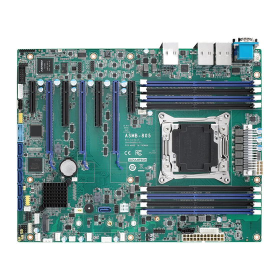
Page 13: Board Layout, Jumpers And Connectors
Board Layout, Jumpers and Connectors Connectors on the ASMB-805 are linked to external devices such as hard disk drives. In addition, ASMB-805 has a number of jumpers that are used to configure the system for specific applications. The tables below list the functions of each jumper and connector. Later sections in this chapter give instructions for setting jumpers. - Page 14 Note! The pictures shown are for illustration purpose only. Actual product may vary due to product enhancement. Table 1.2: Onboard LAN LED Color Definition 10/100 Mbps and 1 Gbps LAN Link/Activity LED Scheme LAN1 & LAN2 (1G) Left LED Right LED Link Green 10 Mbps...
- Page 15 Table 1.4: Connectors COM2 Serial port RS-232 CPUFAN0 CPU FAN connector DIMMA1, DIMMA2, DIMMB1, DIMMB2, DDR4 slot from CPU DIMMC1, DIMMC2, DIMMD1, DIMMD2 Ex_THR1 Connector for external thermistor GPIO1 GPIO connector HDAUD1 Audio header JFP1, JFP2, JFP3 Front panel header KBMS1 External keyboard and mouse connector (6 pin) RJ-45 LAN port 1 + USB 3.0 port...
-
Page 16: Block Diagram
Table 1.5: Onboard LED Description LED Definition Off: On (Green): +5V_LED1 Power on LED Power off System on On (Green): Off: +5V_SB_LED1 Standby LED System on, in sleep mode, or No input AC Power in soft-off mode BMC heartbeat LED Blinking (Green): BMC_HBLED1 (ASMB-805I SKU) -
Page 17: Memory Installation
Memory Installation Memory performance is affected by different DIMM configurations. To reach optimal memory interleaving, be sure to install identical DIMM types with the same size, speed, and number of ranks on those memory slots corresponding to the correct pro- cessor. -
Page 18: Processor Installation
Processor Installation Step 1 Press the first lever and move it sideways slightly until it is released from the reten- tion tab. Step 2 Press the other lever and move it sideways slightly until it is also released from the retention tab. - Page 19 Step 3 Lift the load plate. ASMB-805 User Manual...
- Page 20 Step 4 Place the processor on the CPU socket and align the triangle mark printed on the processor and CPU socket. ASMB-805 User Manual...
- Page 21 Step 5 Close the load plate over the CPU. Push down both levers and insert them under the retention tabs ensuring the edge of the load plate is fixed securely by both levers. ASMB-805 User Manual...
- Page 22 Step 6 Install the CPU cooler on the top of the CPU and make sure air flow direction is same as following arrow indication. Tighten the screws in diagonal sequence. Air flow direction of CPU cooler P/N 196006584N011 Air flow direction of CPU cooler P/N 1960055362N001 ASMB-805 User Manual...
-
Page 23: Chapter 2 Connections
Chapter Connections... -
Page 24: Introduction
(USB 2.0) / 5Gbps (USB 3.0) and fuse protection are supported. The USB interface can be disabled in the system BIOS setup. ASMB-805 series is equipped with two high-performance 1000 Mbps Ethernet LANs. They are supported by all major net- work operating systems. -
Page 25: Vga Connector (Vga1)
VGA Connector (VGA1) The ASMB-805I equips a VGA interface that can drive conventional CRT and LCD displays. VGA1_COM1 VGA1 Serial Ports (COM1~2) The ASMB-805 offers one serial port on the rear plate and one 2.50mm onboard with 2 x 5-pin pitch. M1~2 VGA1_COM1 COM2... -
Page 26: Ps2 Keyboard And Mouse Connectors (Kbms1)
PS2 Keyboard and Mouse Connectors (KBMS1) The 6-pin KBMS1 connector is for additional keyboard & mouse device usage. KBMS1 KBMS1 CPU Fan Connector (CPUFAN0) This connector supports cooling fans that draw up to 1.5A (18W). CPUFAN0 CPUFAN0 ASMB-805 User Manual... -
Page 27: System Fan Connector (Sysfan0~3, Rear_Fan)
System Fan Connector (SYSFAN0~3, REAR_FAN) REAR_FAN SYSFAN0~3 REAR_FAN SYSFAN3 SYSFAN2 SYSFAN1 SYSFAN0 Front Panel Connector (JFP1, JFP2, JFP3) There are several external switches and LEDs to monitor and control ASMB-805. JFP1/2/3 ASMB-805 User Manual... -
Page 28: Power Led (Jfp3)
2.8.1 Power LED (JFP3) JFP3 pin 1 and pin 3 are for the power LED. Refer to Appendix B for detailed infor- mation on the pin assignments. If an ATX power supply is used, the system’s power LED status will be as indicated. Table 2.1: ATX Power Supply LED Status ACPI Power Mode LED (ATX power) -
Page 29: Case Open (Jcase1)
The default function is disabled and Pin 1-2 is bridged by a jumper cap. JCASE1 JWDT1 2.10 SATA SGPIO (SGPIO1) Connect SGPIO1 to HDD backplane in Advantech HPC chassis to analyze HDD LED status. SGPIO1 SGPIO1 ASMB-805 User Manual... -
Page 30: Front Panel Lan Indicator Connector (Lanled1)
2.11 Front Panel LAN Indicator Connector (LANLED1) LANLED1 LANLED1 2.12 SATA (SATA0~5) ASMB-805 features ten serial ATA III interfaces (up to 600 MB/s) which eases cabling to hard drives with thin and long cables. SATA0 SATA1 SATA2 SATA3 SATA0~5 SATA4 SATA5 ASMB-805 User Manual... -
Page 31: Connector (M2_2280_1)
2.13 M.2 Connector (M2_2280_1) The M.2 connector supports the PCIe card in 22110, 2280, and 2242 form factor (three screw holes available). M2_2280_1 M2_2280_1 2.14 PCIe Expansion Slots & PCIe switch(JPRSNT1/ JPRSNT2) ASMB-805 provides seven expansion slots that can support three double-deck cards. -
Page 32: Compatible Riser Cards
Slot Length Link PCI-E Generation PCIe link from SLOT1 PCI-E x4 PCI-E x4 SLOT2 PCI-E x16 PCI-E x16 SLOT3 PCI-E x8 PCI-E x8 or no link SLOT4 PCI-E x16 PCI-E x8 or x16 SLOT5 PCI-E x8 PCI-E x8 or no link SLOT6 PCI-E x16 PCI-E x8 or x16... -
Page 33: Hd Audio Interface Connector (Hdaud1)
HDB1E) installation. HDAUD1 HDAUD1 2.17 LPC Connector (LPC2) ASMB-805 has one LPC connector that can be used to install Advantech's TPM module (P/N: PCA-TPM-00A1E, PCA-TPM-00B1E) for security management and Advantech's COM module (P/N: PCA-COM232-00A1E, PCA-COM485-00A1E). LPC2 LPC2 ASMB-805 User Manual... -
Page 34: Cmos Clear And Me Update Connector (Jcmos1, Jme1)
2.18 CMOS Clear and ME Update Connector (JCMOS1, JME1) Setting jumper from pin 1-2 to pin 2-3, then back to pin 1-2 to reset CMOS data and enable ME update. JME1 JME1 JCMOS1 JCMOS1 2.19 PMBUS Connector (PMBUS1) PMBus monitors the power supplies, fans, and temperatures. PMBUS1 PMBUS1 ASMB-805 User Manual... -
Page 35: Front Panel Smbus Connector (Smbus1)
2.20 Front Panel SMBUS Connector (SMBUS1) SMBUS1 SMBUS1 2.21 IPMI Module Connector (BMC_CN1) Enabling IPMI feature through BMC_CN1 and BMC_CN2. The BMC Module has already been pre-installed on ASMB-805I sku. BMC_CN2 BMC_CN1 BMC_CN1 ASMB-805 User Manual... -
Page 36: Volt1 Connector (Volt1)
2.22 VOLT1 Connector (VOLT1) VOLT1 connects to the alarm board on the Advantech chassis. These alarm boards give warnings if a power supply or fan fails, if the chassis overheats, or if the back- plane malfunctions. VOLT1 VOLT1 2.23 GPIO Connector (GPIO1) -
Page 37: Intel Virtual Raid (Vroc1)
2.24 Intel Virtual RAID (VROC1) Intel VROC license key of VMD allows NVMe SSDs to connect via PCIe and directly manages the CPU for better RAID performance. Enable NVMe SSD RAID, hot-plug and LED management features via VROC connector. VROC1 VROC1 2.25 NVMe RAID LED Control (PEHP1) -
Page 38: System Temperature Monitor (Rt1, Ex_Thr1, Jthr_Sel1)
2.26 System Temperature Monitor (RT1, EX_THR1, JTHR_SEL1) Select system temperature source by adjusting jumper JTHR_SEL1. Close pin 1-2 (default) to set up as onboard thermistor (RT1). Close pin 2-3 to set up as external thermistor (EX_THR1). Connect external thermistor to the suitable location in sys- tem. -
Page 39: Ami Bios
Chapter AMI BIOS... -
Page 40: Introduction
Introduction With the AMI BIOS Setup program, you can modify BIOS settings and control the special features of your computer. The Setup program uses a number of menus for making changes and turning the special features on or off. This chapter describes the basic navigation of the ASMB-805 setup screens. -
Page 41: Bios Setup
BIOS Setup 3.2.1 Main Menu Press <Del> during bootup to enter AMI BIOS CMOS Setup Utility; the Main Menu will appear on the screen. Use arrow keys to select among the items and press <Enter> to accept or enter the sub-menu. The Main BIOS setup screen has two main frames. -
Page 42: Advanced Bios Features Setup
3.2.2 Advanced BIOS Features Setup Select the Advanced tab from the ASMB-805 setup screen to enter the Advanced BIOS setup screen. You can select any of the items in the left frame of the screen, such as CPU configuration, to go to the sub menu for that item. You can display an Advanced BIOS Setup option by highlighting it using the <Arrow>... - Page 43 3.2.2.1 PCH-FW Configuration 3.2.2.2 Trusted Computing Security Device Support Enables or disables BIOS support for security devices. ASMB-805 User Manual...
- Page 44 Note! Purchase Advantech’s LPC TPM module to enable TPM function. P/N: PCA-TPM-00A1E or PCA-TPM-00B1E. 3.2.2.3 ACPI Settings Enable Hibernation Enable or disable hibernation feature. PowerOn By Modem Enable or disable power on by modem feature. ASMB-805 User Manual...
- Page 45 3.2.2.4 IT8528 EC Super IO Configuration Serial Port 1 Configuration – Serial Port Enable or disable serial port 1. – Change Settings To select an optimal setting for serial port 1. ASMB-805 User Manual...
- Page 46 Serial Port 2 Configuration – Serial Port Enable or disable serial Port 2. – Change Settings To select an optimal setting for serial port 2. ASMB-805 User Manual...
- Page 47 3.2.2.5 IT8528 HW Monitor Watchdog Timer Enable or disable the watchdog timer function. CPU ACPI Shutdown Temperature Enable or disable the ACPI shutdown temperature threshold. When the system reaches the shutdown temperature, it will be automatically shut down by ACPI OS to protect the system from overheat damage.
- Page 48 3.2.2.6 Serial Port Console Redirection ASMB-805 User Manual...
- Page 49 COM1 Console Redirection Settings – Terminal Type Select a terminal type to be used for console redirection. Options available: VT100/VT100+/VT-UTF8/ANSI. – Bits Per Second Select the baud rate for console redirection. Options available: 9600/19200/38400/57600/115200. – Data Bits Options available: 7/8 –...
- Page 50 – VT-UTF8 Combo Key Support Enable VT-UTF8 combination key support for ANSI/VT100 terminals – Recorder Mode When this mode enabled, only text will be sent; this is to capture terminal data. Options available: Enabled/Disabled. – Resolution 100x31 Enables or disables extended terminal resolution. –...
- Page 51 Console Redirection Settings – Terminal Type Set as "VT100", "VT100+", "VT-UTF8", or "ANSI". "VT-UTF8" is the default setting. – Bits Per Second To select serial port transmission. Speed must be matched on the other side. It can be set as "9600", "19200", "57600", or "115200". "115200" is the default setting.
- Page 52 – VT-UTF8 Combo Key Support Enable VT-UTF8 combination key support for ANSI/VT100 terminals – Recorder Mode When this mode enabled, only text will be sent; this is to capture terminal data. Options available: Enabled/Disabled. – Resolution 100x31 Enables or disables extended terminal resolution. –...
- Page 53 3.2.2.8 USB Configuration Legacy USB Support This is for supporting USB device under a legacy OS such as DOS. When choosing "Auto", the system will automatically detect if any USB device is plugged into the computer and enable USB legacy mode when a USB device is plugged, or disable USB legacy mode when no USB device is attached.
- Page 54 3.2.2.9 CSM Configuration CSM Support Enable or disable UEFI CSM (Compatibility Support Module) to support a leg- acy PC boot process. GateA20 Active This items is useful when RT code is executed above 1MB. When it's set as "Upon Request", GA20 can be disabled using BIOS services.
- Page 55 3.2.2.10 NVMe Configuration Set up NVMe device options. 3.2.2.11 Network Stack Configuration ASMB-805 User Manual...
-
Page 56: Chipset
3.2.3 Chipset 3.2.3.1 PCH-IO Configuration PCIe M.2 Slot Configuration Enable or disable the PCI Express root port. ASMB-805 User Manual... - Page 57 PCH SATA Configuration – SATA Controller Enable or disable SATA devices. – SATA Mode Selection Set as AHCI or Intel RSTe Premium when SATA Controllers are enabled. – Support sALPM Enable or disable Aggressive Link Power Management (ALPM) protocol for AHCI SATA devices.
- Page 58 HD Audio Configuration Enables or disables audio devices Note! Purchase Advantech’s audio module to have audio function. P/N: PCA- AUDIO-HDA1E or PCA-AUDIO-HDB1E. ASMB-805 User Manual...
- Page 59 Networking – LAN1 Controller Enable or disable Intel I210 controller support. – LAN1 PXE OpROM Enable or disable Boot option for Intel I210 controller. – LAN2 Controller Enable or disable Intel I210 controller support. – LAN2 PXE OpROM Enable or disable Boot option for Intel I210 controller. Restore AC Power Loss ...
-
Page 60: Platform Configuration
3.2.4 Platform Configuration 3.2.4.1 Miscellaneous Configuration VGA Priority Determine priority between onboard and 1st off-board device found. RTC Wake System form S5 Enable or disable system wake on alarm event. ASMB-805 User Manual... -
Page 61: Socket Configuration
3.2.5 Socket Configuration 3.2.5.1 Processor Configuration Per-Socket Configuration Use this to select how many processor cores you want to activate. ASMB-805 User Manual... - Page 62 Hyper-threading [All] Enable or disable Intel Hyper Threading technology. Enable or disable Intel Virtual Machine Extensions (VMX) for IA-32 processors that support Intel® Vanderpool Technology Enable SMX Enable or disable Safer Mode Extensions. Safer Mode Extensions (SMX) pro- vide a means for system software to launch an MLE and establish a measured environment within the platform to support trust decisions by end users.
- Page 63 Memory Technology Display memory topology with DIMM population information. 3.2.5.3 IIO Configuration Socket0 Configuration PCIe port bifurcation control and select target link speed as Gen1, Gen2, Gen3. ASMB-805 User Manual...
- Page 64 ASMB-805 User Manual...
- Page 65 Intel VT for Directed I/O (VT-d) Enable or disable Intel Virtualization Technology for Directed I/O. Intel VMD technology Enable or disable Intel Volume Management Device Technology. ASMB-805 User Manual...
- Page 66 PCIe Hot Plug Enable or disable PCIe hot plug globally. PCI-E ASPM Support (Global) Enable or disable ASPM support for all downstream devices. 3.2.5.4 Advanced Power Management Configuration ASMB-805 User Manual...
- Page 67 CPU P State Control CPU C State Control ASMB-805 User Manual...
-
Page 68: Sever Management (Asmb-805I Only)
Package C State Control 3.2.6 Sever Management (ASMB-805I only) BMC Support Enable or disable interfaces to communicate with BMC. Wait for BMC ASMB-805 User Manual... - Page 69 If enabled, motherboard will wait 30 ~ 60 seconds until BMC module boots up completely. After that, the normal BIOS post screen will be displayed. If disabled, motherboard will not wait for BMC module's response. Wait for BMC counter Initialize host to BMC interfaces.
- Page 70 3.2.6.2 BMC Self Test Log Erase Log Erase log options. When Log is Full Select the action to be taken when log is full. 3.2.6.3 BMC Network Configuration ASMB-805 User Manual...
-
Page 71: Security
Configuration Address Source Select to configure LAN channel parameters statically or dynamically (by BMC). Unspecified option will not modify any BMC network parameters during BIOS phase. 3.2.7 Security Note! With AC power & Battery. Short CMOS1 Jumper: Date/Time & Password: Keep Setting: reset to default AC power and CMOS battery are removed. -
Page 72: Boot
3.2.8 Boot Setup Prompt Timeout Number of seconds to wait for setup activation key. Bootup NumLock State Select the keyboard NumLock state as "On" or "Off". Quiet Boot Enable or disable quiet boot option. Boot Option Priorities ... -
Page 73: Save & Exit
3.2.9 Save & Exit Save Changes and Exit Exit system setup after saving the changes. Discard Changes and Exit Exit system setup without saving any changes. Save Changes and Reset Reset the system after saving changes. Discard Changes and Reset ... - Page 74 ASMB-805 User Manual...
-
Page 75: Chipset Software Installation Utility
Chapter Chipset Software Installation Utility... -
Page 76: Before Beginning
The chipset driver is used for the following versions of Windows, and it has to be installed before installing all the other drivers: Windows 10 Windows Series Driver Setup Enter the Advantech support website, then search product ASMB-805. You can see all necessary drivers. Windows 10 Driver Setup ASMB-805 User Manual... -
Page 77: Graphic Setup
Chapter Graphic Setup... -
Page 78: Introduction
Introduction Install the ASPEED VGA driver to enable this function, which includes the following features: 32-bit 2D graphics engine on board for normal use. 64 MB RAM for this chip, the highest resolution is 1920x1200. Windows Series Driver Setup Insert the driver CD into your system's CD-ROM drive. -
Page 79: Lan And Rste Raid
Chapter LAN and RSTe RAID... -
Page 80: Lan Configuration
The integrated Intel gigabit Ethernet controller supports all major network operating systems. However, the installation procedure varies with different operating systems. 6.1.2 Windows Series Driver Setup Enter the Advantech support website, then search product ASMB-805. You can see all necessary drivers. Windows 10 Driver Setup ASMB-805 User Manual... -
Page 81: Sata & Pcie Ssd Raid
Microsoft Windows Operating System Software User's Guide" file download, 2.For the hotfix file download, please visit Microsoft website. 6.2.2 Windows Series Driver Setup Enter the Advantech support website, then search product ASMB-805. You can see all necessary drivers. Windows 10 Driver Setup ASMB-805 User Manual... - Page 82 ASMB-805 User Manual...
-
Page 83: Appendix A Programming The Watchdog Timer
Appendix Programming the Watchdog Timer... -
Page 84: Watchdog Timer Overview
The ASMB-805’s watchdog timer can be used to monitor system software operation and take corrective action if the software fails to function within the programmed period. This section describes the operation of the watchdog timer and how to pro- gram it. Watchdog Timer Overview The watchdog timer is built in to the EC controller IT8528E. - Page 85 Write 0x57 to 0x299 port Watchdog Event Wait IBF clear 0x29A, BIT1, = 0 Write 0x04 to 0x299 port (Warm) Reset event Wait IBF clear 0x29A, BIT1, = 0 Write 0x28 to 0x29A Start watchdog Wait 1 ~ 9 Wait IBF clear 0x29A, BIT1, = 0 Write 0x29 to 0x29A Stop watchdog...
- Page 86 ASMB-805 User Manual...
-
Page 87: Appendix B I/O Pin Assignments
Appendix I/O Pin Assignments... -
Page 88: Usb2.0 Header (Usb9_10, Usb13_14)
USB2.0 Header (USB9_10, USB13_14) Table B.1: USB Header (USB9_10, USB13_14) Signal Signal USB_VCC5 USB_VCC5 USB_D- USB_D- USB_D+ USB_D+ USB3.0 Header (USB3_78) Table B.2: USB Header (USB78) Signal Signal +5 V STDA_SSRX- STDA_SSRX+ STDA_SSRX-TX- STDA_SSRX+TX+ STDA_SSRX+TX+ STDA_SSRX-TX- STDA_SSRX+ STDA_SSRX- +5 V ASMB-805 User Manual... -
Page 89: Vga Connector (Vga1)
VGA Connector (VGA1) Table B.3: VGA Connector (VGA1) Signal Signal GREEN BLUE H-SYNC V-SYNC RS-232 Interface (COM1) Table B.4: RS-232 Connector (COM1) Signal ASMB-805 User Manual... -
Page 90: Rs-232 Interface (Com2)
RS-232 Interface (COM2) Table B.5: RS-232 Connector (COM2) Signal External Keyboard Connector (KBMS2) Table B.6: External Keyboard Connector (KBMS2) Signal KB CLK KB DATA MS DATA MS CLK ASMB-805 User Manual... -
Page 91: System & Cpu Fan Power Connector
System & CPU Fan Power Connector (CPUFAN0, SYSFAN0~3, REAR_FAN) Table B.7: CPU FAN Connector (CPUFAN0) CPUFAN0 +12V CPU_TACH CPU0_PWM Table B.8: SYS FAN Connector (SYSFAN0~3, REAR_FAN) SYS FAN0 SYS FAN1 SYS FAN2 SYSFAN3 REAR_FAN +12V +12V +12V +12V +12V FAN0_TACH FAN1_TACH FAN2_TACH FAN3_TACH... -
Page 92: External Speaker Connector (Jfp2)
External Speaker Connector (JFP2) 7 10 Table B.10: External Speaker Connector (JFP2) Function SPK+ SPK- B.10 Reset Connector (JFP1) 9 12 Table B.11: Reset Connector (JFP1) Signal RESET B.11 HDD LED Connector (JFP1) Table B.12: HDD LED Connector (JFP1) Signal HDD_LED+ HDD_LED- ASMB-805 User Manual... -
Page 93: Atx Soft Power Switch (Jfp1)
B.12 ATX Soft Power Switch (JFP1) Table B.13: ATX Soft Power Switch (JFP1) Signal PWR-BTN B.13 SMBus Connector (SMBUS1) Table B.14: Front panel SMBus Connector (SMBUS1) Signal +3.3V_AUX SMB_SCL_FRU SMB_SDA_FRU B.14 Audio Connector (HDAUD1) Table B.15: Front Panel Audio Connector (HDAUD1) Signal Signal +V5_AUDIO... -
Page 94: Alarm Board Connector (Volt1)
B.15 Alarm Board Connector (VOLT1) Table B.16: Alarm Board Connector (VOLT1) Signal Signal 5VSB +3.3V -12V +12V B.16 Case Open Connector (JCASE1) Table B.17: Case Open Connector (JFP1) Signal CASEOP B.17 Front Panel LAN LED Connector (LANLED1) Table B.18: LAN LED Connector (LANLED1) Signal Signal LAN1_ACT#... -
Page 95: Sata Sgpio Connector (Sgpio1)
B.18 SATA SGPIO Connector (SGPIO1) Table B.19: SATA SGPIO Connector (SGPIO1) Signal SCLOCK_PCH SLOAD_PCH SDATAOUT0_PCH SDATAOUT1_PCH B.19 LPC Connector (LPC2) Table B.20: LPC Connector (LPC2) Signal Signal CLK_33M_TPM LPC_AD1 PLTRST_LPC LPC_AD0 LPC_FRAME +3.3V LPC_AD3 LPC_AD2 SMB_SCL_LPC SERIRQ_PCH SMB_SDA_LPC +5V_AUX B.20 Clear CMOS Connector (JCMOS1, JME1) Table B.21: Clear CMOS Connector (JCMOS1, JME1) JCMOS1... -
Page 96: Pmbus Connector (Pmbus1)
B.21 PMBUS Connector (PMBUS1) Table B.22: PMBUS Connector (PMBUS1) Signal SMB_SCL_PM SMB_SDA_PM SMB_ALT_PM +3.3V B.22 GPIO Connector (GPIO1) Table B.23: GPIO Connector (GPIO1) Signal Signal SIO_GPIO0 SIO_GPIO4 SIO_GPIO1 SIO_GPIO5 SIO_GPIO2 SIO_GPIO6 SIO_GPIO3 SIO_GPIO7 VCC_GPIO0 ASMB-805 User Manual... - Page 97 ASMB-805 User Manual...
- Page 98 No part of this publication may be reproduced in any form or by any means, electronic, photocopying, recording or otherwise, without prior written permis- sion of the publisher. All brand and product names are trademarks or registered trademarks of their respective companies. © Advantech Co., Ltd. 2020...
Need help?
Do you have a question about the ASMB-805 Series and is the answer not in the manual?
Questions and answers