
Related Manuals for Comba Telecom MRU-4500

Summary of Contents for Comba Telecom MRU-4500
- Page 1 MRU-4500 USER MANUAL MRU-4500 5W QE: 1-0-0 Comba Telecom Ltd.
- Page 2 USER MANUAL FOR COMFLEX-5H00 1W2W The information contained herein is the responsibility of and is approved by the following, to whom all enquiries should be directed in the first instance: This is an unpublished work the copyright in which vests in Comba International ("Comba").
-
Page 3: Table Of Contents
USER MANUAL FOR COMFLEX-4500 5W CONTENTS Section Page CONTENTS ............................... 3 INDEX TO FIGURES AND TABLES ........................4 HISTORY ................................6 GLOSSARY OF TERMS ............................7 SAFETY NOTICES AND ADMONISHMENTS ....................... 8 GENERAL INFORMATION ..........................9 EQUIPMENT DESCRIPTION .......................... 11 SYSTEM DIAGRAM ............................ -
Page 4: Index To Figures And Tables
USER MANUAL FOR COMFLEX-4500 5W INDEX TO FIGURES AND TABLES Figure 1: Master Unit (MU) ............................9 Figure 2: Remote Unit (RU) and RU PSU ......................10 Figure 3: System Diagram ............................11 Figure 4: SISO Typical Application 1:4 ........................11 Figure 5: MIMO Typical Application 1:4 ......................... - Page 5 USER MANUAL FOR COMFLEX-4500 5W Figure 54: [Firmware] Screen – Pop-up Window 2 ....................49 Figure 55: [Firmware] Screen - Swap ........................49 Figure 56: [Firmware] Screen – Module upgrade ....................50 Figure 57: [Management] Screen ........................... 50 Figure 58: Management – Import&Export ......................51 Figure 59: Management –...
-
Page 6: History
USER MANUAL FOR COMFLEX-4500 5W HISTORY Change No. Details Of Change 1-0-0 This user manual first created in Oct 2014 which referred to its Chinese manual MRU01-4500-1001YH. ENU STATUS : 1-0-0 Copyright - refer to title page Page 6... -
Page 7: Glossary Of Terms
USER MANUAL FOR COMFLEX-4500 5W GLOSSARY OF TERMS Automatic Level Control Attenuation Bi-direction Amplifier Base Station Base Transceiver Station Downlink Donor Terminal Fiber Optical Unit Graphic User Interface Identification Low Noise Amplifier Main Control Unit Mobile Terminal MTBF Mean Time Between Failures Master Unit Normally Closed Noise Figure... -
Page 8: Safety Notices And Admonishments
USER MANUAL FOR COMFLEX-4500 5W SAFETY NOTICES AND ADMONISHMENTS This document contains safety notices in accordance with appropriate standards. In the interests of conformity with the territory standards for the country concerned, the equivalent territorial admonishments are also shown. Any installation, adjustment, maintenance and repair of the equipment must only be carried out by trained, authorized personnel. -
Page 9: General Information
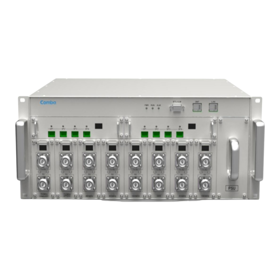
USER MANUAL FOR COMFLEX-4500 5W 1 GENERAL INFORMATION The ComFlex-4500 Medium Power Distributed Antenna System (hereinafter called “ComFlex-4500”) consists of Master Unit (MU) and Remote Unit (RU). The MU includes the MU Chassis, Power Supply Unit (PSU), Fiber Optical Unit (FOU) and RF Unit (RFU). With a modular design, it can support up to 8 independent RF inputs and 8 Remote Units. - Page 10 USER MANUAL FOR COMFLEX-4500 5W Figure 2: Remote Unit (RU) and RU PSU End of Section ENU STATUS : 1-0-0 Copyright - refer to title page Page 10...
-
Page 11: Equipment Description
USER MANUAL FOR COMFLEX-4500 5W 2 EQUIPMENT DESCRIPTION SYSTEM DIAGRAM Optical Fiber Antenna Figure 3: System Diagram On the DL, signals from the BTSs or BDA are converted into optical signals after amplification in the MU.Then the optical signals are transmitted to the RU via optical fiber. The Optical TX/RX Module of RU converts the DL optical signals into RF signals. -
Page 12: Equipment Constitution
USER MANUAL FOR COMFLEX-4500 5W 850MHz 1800MHz 2100MHz 2600MHz 850MHz 1800MHz 2100MHz 2600MHz Figure 5: MIMO Typical Application 1:4 EQUIPMENT CONSTITUTION MU consists of the following parts: Table 1: MU Components Module Description Master Unit Chassis includes eight slots for RF Unit, two slots for Fiber Optical MU01-RACK-E02 Unit, and one slot for Power Supply Unit. - Page 13 USER MANUAL FOR COMFLEX-4500 5W RU consists of the following part: Table 2: RU Components Module Description Remote Unit; A compact and slim design which supports 4 bands, including MRU01-4500 850MHz, 1800MHz, 2100MHz and 2600MHz bands. LRU01-PSU- Remote Power Supply Unit, can be installed on the RU or be installed separately A92W300 on the wall nearby RU.
-
Page 14: Kit Of Part
USER MANUAL FOR COMFLEX-4500 5W KIT OF PART Table 3: Master Unit (MU) KOP Item Image MU Chassis RF Unit (RFU) Fiber Optical Unit (FOU) FOU Dummy Load RFU Dummy Load Power Supply Unit (PSU) Power Supply Cable (13 Feet 1 inch) Communication Cable Right Angle Bracket (for MU 19“rack mounting) - Page 15 USER MANUAL FOR COMFLEX-4500 5W Table 4: Remote Unit (RU) KOP Item Image Remote Unit Remote Power Supply Unit Mounting Rack (for RU wall mounting) Masonry Bolt (set) M8x80 ( for RU concrete wall mounting) Masonry Bolt (set) M8x80 ( for RU PSU concrete wall mounting ) Nuts M10x25, Spring Washers Φ10, Plain Washers Φ10 4 pieces each...
-
Page 16: Installation
USER MANUAL FOR COMFLEX-4500 5W 3 INSTALLATION WARNINGS AND ALERTS Laser Laser light can cause damage to eyes. Laser light is not visible. Viewing it directly does not cause pain. The iris of the eye will not close when viewing a bright light. Consequently, serious damage to the retina of the eye is possible. -
Page 17: Site Planning Considerations
USER MANUAL FOR COMFLEX-4500 5W SITE PLANNING CONSIDERATIONS 3.2.1 SITE PLANNING Site Considerations The MU is designed to be located indoors to facilitate coupling of BTS signals and power supply connections. The input range of MU RF unit is 10~30 dBm. The site consideration for RU is listed below: ... - Page 18 USER MANUAL FOR COMFLEX-4500 5W Manual Handling During transportation and installation, take necessary handling precautions to avoid potential physical injury to the installation personnel and the equipment. 3.2.2 SYSTEM INSTALLATION CHECKLIST Working space available for installation and maintenance for each mounting arrangement. Ensure unrestricted airflow.
-
Page 19: Installation Procedures
Without documentary evidence, a claim cannot be processed. Open and check each package against the packing list. For any shortage, contact Comba Telecom Systems. Do not remove items from packing materials until installation. - Page 20 USER MANUAL FOR COMFLEX-4500 5W Power Supply Unit Fiber Optical Unit Rack RF Unit Redundant Power Supply Unit Optional Li-Battery Unit Optional Modem Unit Figure 6: ComFlex Master Unit Step 1: RF Unit installation: Remove RFU slot cover plate on Chassis, insert RFU and fasten the screws. (Each Unit can be installed in any one of eight RFU slots) ENU STATUS : 1-0-0 Copyright - refer to title page...
- Page 21 USER MANUAL FOR COMFLEX-4500 5W Figure 7: RF Unit Installation Step 2: FOU installation: Remove FOU slot cover plate on Chassis, insert FOU and fasten the screws. (Each Unit can be installed in either one of two FOU slots) Figure 8: FOU Installation Step 3: PSU installation: Remove PSU slot cover plate on the right side of Chassis, insert PSU and fasten the screws.
- Page 22 USER MANUAL FOR COMFLEX-4500 5W Step 4: Optional PSU installation: The optional PSU is installated on the rear panel with four screws. Connect DC 28V power cable to the EXT_PSU connector of the rack shown as below figure, and the grounding wire must conncet to the rack grounding connector.
- Page 23 USER MANUAL FOR COMFLEX-4500 5W Step 5: Optional Li-Battery unit installation: Access the optional Li-Battery unit into the slot on the rear panel and screw it using four M3*8 screws. Connect LI_BAT cable of the unit to the LI_BAT connector of the rack shown as below figure, and screw it.
- Page 24 USER MANUAL FOR COMFLEX-4500 5W Figure 14: Mounting Rack Figure 15: Angle Iron Installation Step2: Slide the MU on to the angle brackets and confirm it is level. ENU STATUS : 1-0-0 Copyright - refer to title page Page 24...
- Page 25 USER MANUAL FOR COMFLEX-4500 5W Figure 16: MU Installation Step 3: Attach the MU onto the rack with the recommended rack screws. Figure 17: Secure the Enclosure Step 4: Finish installation. ENU STATUS : 1-0-0 Copyright - refer to title page Page 25...
- Page 26 USER MANUAL FOR COMFLEX-4500 5W Figure 18: Finish Installaiton 3.3.6 RU WALL MOUNTING RU wall mounting steps are shown below. Step 1: Select the wall mount location according to the following criteria: General surroundings If mounting on dry wall, 0.75 In (min) plywood backboard is required to support the weight of the equipment.
- Page 27 USER MANUAL FOR COMFLEX-4500 5W 6.65 Figure 19: Wall Drilling Dimensions of RU (Unit: inch) Step 3: Attach the mounting rack on a wall. If a concrete wal, use the 4 M10×110 masonry bolts. Two M8x80 Masonry bolts Figure 20: Install Mounting Rack on the Wall Step 4: Ensure the antenna and other connectors are facing down, hang RU onto semicircle slot of mounting rack.c ENU STATUS : 1-0-0...
- Page 28 USER MANUAL FOR COMFLEX-4500 5W Figure 21: Hang RU onto the Mounting Rack Step 5: Tighten the RU on masonry bolts with four M8 *80 nuts. Two M8*80 Masonry bolts Figure 22: Tighten the Screws at the Bottom of RU Step 6: Check the RU installated tightly and the hexagon socket screws tightly be installated on the mouting rack.
- Page 29 USER MANUAL FOR COMFLEX-4500 5W M6*20 hexagon socket screw Figure 23: Finish Installation 3.3.7 Remote PSU Installation Remote PSU should be installed afer RU finish installation. It can be installed on the RU or on the wall nearby RU. Installed on RU Remote PSU should be installed on the right of RU using two M6*10 hexagon socket screws.
- Page 30 USER MANUAL FOR COMFLEX-4500 5W Installed on the wall Step 1: Measure and mark two holes on the wall nearby RU, the max. demision from RU is 0.5m. 4.37 Figure 25: Mounting Rack Installation (Unit: inch) Step 2: Screw two hexagonal masonry bolts M8 x 80 to fasten the PSU on the wall. Figure 26: Remote PSU wall mounting ENU STATUS : 1-0-0 Copyright - refer to title page...
-
Page 31: Equipment Connectors
USER MANUAL FOR COMFLEX-4500 5W EQUIPMENT CONNECTORS The figures below present the connectors of ComFlex MU. Figure 27: MU Front Panel Connectors Figure 28: MU Rear Panel Connectors ENU STATUS : 1-0-0 Copyright - refer to title page Page 31... - Page 32 USER MANUAL FOR COMFLEX-4500 5W Table 5: MU Connections Identifier Functional Description 1. OP1~OP4 SC/APC optical fiber access port 2. LED indicator LED indicator. See Chapter 4 for the description of each indicator. 3. BTS_ALM DB9-F connector for BTS alarm. RJ45 connector connects PC with equipment for local and remote 4.
- Page 33 USER MANUAL FOR COMFLEX-4500 5W Table 6: RU Connections Identifier Functional Description N-Female connector, antenna system connection port SC/APC optical fiber access port EXT_ALM External alarm port. It provides an alarm report interface for other devices to report their alarms to CMS. RS-485 For communication of expansion device For local monitoring and debugging...
-
Page 34: Equipment Connection
USER MANUAL FOR COMFLEX-4500 5W EQUIPMENT CONNECTION 3.5.1 GROUNDING CONNECTION WARNING! This unit must always be grounded. Consult an appropriate electrical inspection authority or an electrician if you are uncertain that suitable grounding is available. Do not connect power before grounding. 3.5.2 MU GROUNDING CONNECTION Step 1: Connect the GND cable to the GND connector and the building EARTH. - Page 35 USER MANUAL FOR COMFLEX-4500 5W Figure 31: RU Grounding 3.5.4 MU CONNECTIONS Step1: Connect the MU OP (optical) port to one of the RU OP port. (NOTE: requires Single Mode fiber with SC/APC connectors; MAXIMUM OPTICAL LOSS = 6.5dBo) Step 2: For duplex application, connect the MU RFU TX/RX port to the RF Source (BTS or BDA). For simplex application, connect the MU RFU TX/RX port to the RF Source downlink, and then connect MU RFU RX port with RF Source uplink.
- Page 36 USER MANUAL FOR COMFLEX-4500 5W Power Connection Figure 33: MU Power Connection (Rear Panel) 3.5.5 RU CONNECTION Step 1: Connect the RU OP (optic) port to one of the OP port located on MU FOU front panel. Step 2: Connect ANT port to a broadband antenna. Step 3: Connect DC28V port of RU to DC28V port of remote PSU.
- Page 37 USER MANUAL FOR COMFLEX-4500 5W AC Power connection AC 100V-240V 50Hz/60Hz DC 28V DC power connection – to RU Figure 35: Remote PSU Connction 3.5.6 RU EXTERNAL ALARM CONNECTION For RU, this is connector for external alarm. The following figure and table show the pin allocation and definition.
- Page 38 USER MANUAL FOR COMFLEX-4500 5W BTS_OPEN BTS_ COM BTS_CLOSE Figure 37: Pins Allocation for “BTS_ALM” Port Table 8: Pin Definition of “BTS_ALM” Port Pin Number Definition Description BTS_OPEN Connects to the open terminal of the voltage free relay. BTS_COM Connects to the common terminal of the voltage free relay. BTS_CLOSE Connects to the close terminal of the voltage free relay.
-
Page 39: Commissioning
USER MANUAL FOR COMFLEX-4500 5W 4 COMMISSIONING PRE-COMMISSIONING TASKS After equipment installation, perform the following steps before equipment powering and commissioning, check that the expected voltage, current, and power levels do not violate any ratings. Double check all connections including ground before applying power. Do not manipulate circuits or make changes when power is applied: ... -
Page 40: Digital Display Indicators
USER MANUAL FOR COMFLEX-4500 5W DIGITAL DISPLAY INDICATORS 4.3.1 DIGITAL DISPLAY ON RFU The digital display tube on RFU shows the DL input power. The range of DL input power shown on the display tube is from -19 to 33 (dBm), when DL input powe is lower than -19dBm, it will show L, when DL input powe is higher than 33, it will display H. - Page 41 USER MANUAL FOR COMFLEX-4500 5W Figure 39: Optical Port No. and Digital Display Table 12: FOU Digital Display Figure Optical Loss 0~9dBo > 9dBo End of Section ENU STATUS : 1-0-0 Copyright - refer to title page Page 41...
-
Page 42: Web Gui
USER MANUAL FOR COMFLEX-5H00 1W2W 5 WEB GUI ComFlex can be monitored and controlled by WEB GUI, follow below contents to achive system parameter setting and commissioning. WEB GUI CONNECTION Step 1: Connect MU OMT port to PC RJ45 port with the supplied Ethernet cable to set up a physical connection. - Page 43 USER MANUAL FOR COMFLEX-5H00 1W2W Figure 42: Input IP Address Step 4: Input User Name: admin; Password (default password: admin). Click [Log in]. Figure 43: Input User Name and Password ENU STATUS : 1-0-0 Copyright - refer to title page Page 43...
-
Page 44: Web Gui Introduction
USER MANUAL FOR COMFLEX-5H00 1W2W WEB GUI INTRODUCTION After log in, the Web GUI main screen will appear. Figure 44: Web GUI Main Screen On Comba Web GUI Home page, there are four Menu bars: [Devices], [Commissioning], [Firmware] and [Management]. 5.2.1 [DEVICES] The [Devices] page shows the actual connection diagram of MU and RU. - Page 45 USER MANUAL FOR COMFLEX-5H00 1W2W MU Main Management Screen This part shows MU basic information This part shows MU alarm status Click here to enable/disable alarm Figure 46: MU Device - Monitoring Unit Optical Unit Management Screen Figure 47: MU Device - Optical Unit Note: MU transmit optical power is -4~-2dBm.
- Page 46 USER MANUAL FOR COMFLEX-5H00 1W2W RF Unit Management Screen Figure 48: MU Device - RF Unit Remote Unit Management Screen Click RU photo, users can visit RU directly. Make sure two steps are done before visit RU: RU and MU are connected by optical fiber. ...
-
Page 47: Commissioning]
USER MANUAL FOR COMFLEX-5H00 1W2W It will reset PA and then re-detect the PA output power and reflected power, if they are normal, the PA Service Status will turn to Normal, if PA output power or reflected power is still over the threshold, PA Service Status will turn to Recovery again. -
Page 48: Firmware]
USER MANUAL FOR COMFLEX-5H00 1W2W 5.2.3 [FIRMWARE] There are two functions on the [Firmware] bar: [upgrade] and [swap]. [Upgrade] is used to upgrade software, and [Swap] is to replace current firmware version to the previous one. Follow steps shown in below figure to upgrade firmware. Step1: select Step2: Click to device... - Page 49 USER MANUAL FOR COMFLEX-5H00 1W2W Step 5: Wait for 2~4 minutes while MU/RU is being reset. Figure 54: [Firmware] Screen – Pop-up Window 2 Step 6: Clear browsing history and cookies from browser. NOTE: For MU software upgrade, users need to re-login Web GUI after reset is done. Follow steps shown in below figure to Swap firmware.
-
Page 50: Management]
USER MANUAL FOR COMFLEX-5H00 1W2W Step1: Click to select software that to be updated Step2: Click to upgrade software Figure 56: [Firmware] Screen – Module upgrade 5.2.4 [MANAGEMENT] Other parameters can be configured on [Management] page. Select device page Click here to enter corresponding page Figure 57: [Management] Screen ENU STATUS : 1-0-0... - Page 51 USER MANUAL FOR COMFLEX-5H00 1W2W There are thirteen function bar list in the left side of the [Mangement] page. Below figures are the introduction of each function bar. Inport&Export Select a device, the device information will show Parameter configurations can be input and output in this page Figure 58: Management –...
- Page 52 USER MANUAL FOR COMFLEX-5H00 1W2W IP Setting Configure MU IP address for remote monitoring of MU Figure 59: Management – IP Setting Note: Here the device IP Address CANNOT be set as 192.168.8.* SMS Setting Figure 60: Management – SMS Setting ENU STATUS : 1-0-0 Copyright - refer to title page Page 52...
- Page 53 USER MANUAL FOR COMFLEX-5H00 1W2W Maintenance Figure 61: Management – Maintenance Security Figure 62: Management – Security Click , [Modify Password] window will pop-up. ENU STATUS : 1-0-0 Copyright - refer to title page Page 53...
- Page 54 USER MANUAL FOR COMFLEX-5H00 1W2W Figure 63: Modify Password Note: Username cannot be modified. Device Reset Select a device, the device information will show Clear all history alarms Reset Device Figure 64: Management – Device Reset Device Reset Note: process will last about 2~4 minutes.
- Page 55 USER MANUAL FOR COMFLEX-5H00 1W2W PA Reset Only RU has PA reset function Each band can be reset separately Figure 65: Management – PA Reset Note: PA will be turned off by software when PA output power or (VSWR) reflected power is exceed the threshold.
- Page 56 USER MANUAL FOR COMFLEX-5H00 1W2W Device Scanning Figure 67: Management – Device Scanning Note: This Step is the same as step1 of [Commissioning]. Running scanning, software will allocate an ID to RU so that MU can identify and visit it. ...
- Page 57 USER MANUAL FOR COMFLEX-5H00 1W2W Report Figure 69: Management – Report License Device frequency band authorization status Figure 70: Management – License ENU STATUS : 1-0-0 Copyright - refer to title page Page 57...
-
Page 58: Commissioning Procedure
USER MANUAL FOR COMFLEX-5H00 1W2W Alarm Log Figure 71: Management – Alarm Log COMMISSIONING PROCEDURE To complete the installation and commissioning, users need to follow the steps below. Step 1: Click Menu bar [Commissioning] on home page, a work flow will show up. Figure 72: Commissioning Procedure - Start Step 2: Click to start RU device scan, this step will take about 1 minute. - Page 59 USER MANUAL FOR COMFLEX-5H00 1W2W Figure 73: Commissioning Procedure – Device Scan Step 3: Click to enter to Params Setting page. Click , users can set the device information and system time. Figure 74: Commissioning Procedure – Params Setting ENU STATUS : 1-0-0 Copyright - refer to title page Page 59...
- Page 60 USER MANUAL FOR COMFLEX-5H00 1W2W Figure 75: Dev Info & Date/Time Dev Info mainly used to record device location and Date/Time provid a time reference. Mouse click the Config Value of Date/Time to auto receive the computer time. Step 4: Click to enter to the page to select folw to continue.
- Page 61 USER MANUAL FOR COMFLEX-5H00 1W2W system gain will be a little deviation with normal valuer, so the final output power will be not same with the target DL output power. NOTE: Make sure all the ANT ports of RUs are connected with dummy load or antenna system before proceeding to step 5.
- Page 62 USER MANUAL FOR COMFLEX-5H00 1W2W Figure 78: Commissioning Procedure – Automatic Calibration Select RU and frequency to calibrate Figure 79: Commissioning Procedure – Manual Calibration ENU STATUS : 1-0-0 Copyright - refer to title page Page 62...
- Page 63 USER MANUAL FOR COMFLEX-5H00 1W2W Figure 80: Commissioning Procedure –Calibration Finish Step 6: Click to enter to MU Setup page after finishing Calibration. Figure 81: Commissioning Procedure – MU Setup Click to set band related information. ENU STATUS : 1-0-0 Copyright - refer to title page Page 63...
- Page 64 USER MANUAL FOR COMFLEX-5H00 1W2W Figure 82: MU Frequency Band Table Three parameters need to be set in this step. Operator Info: record the operator information of this RU unit. RF Switch: Set the RF switch status of this RF unit. ...
- Page 65 USER MANUAL FOR COMFLEX-5H00 1W2W Figure 83: Commissioning Procedure – RU Setup Click to set band related information of RU. Figure 84: RU Frequency Band Table Two parameters need to be set in this step. RF Switch: Set the RF switch status of Remote Unit. ...
- Page 66 USER MANUAL FOR COMFLEX-5H00 1W2W Step 8: Click to enter to [Finish] page after finishing RU setup. Note: As the system calibration process is calibrated for single channel, so if there is more than one same band input, because of the power superposition, the band total output power will higer than target DL output power after the calibration is complete.
-
Page 67: Alarms And Troubleshooting
USER MANUAL FOR COMFLEX-5H00 1W2W 6 ALARMS AND TROUBLESHOOTING ALARMS Table 14: MU Alarm List Alarm List Alarm Condition Alarm when equipment temperature is higher than the threshold, otherwise normal; Over-Temperature Alarm Alarm judgment period: 3 minutes by default; ... -
Page 68: Troubleshooting
USER MANUAL FOR COMFLEX-5H00 1W2W TROUBLESHOOTING Following installation and commissioning, occasional operation tasks to handle alarms may be required: Table 16: MU Alarms Diagnosis Alarm condition Diagnosis Check device temperature on WEB GUI Over- If device temperature is over threshold, make sure environment temperature is Temperature within the envireonment temperature range that MU supported (0~40℃... -
Page 69: Appendices
USER MANUAL FOR COMFLEX-5H00 1W2W 7 APPENDICES APPENDIX A: TOOLS FOR INSTALLATION AND MAINTENANCE The following tools (not included in package) are required for installation or routine maintenance: Power Drill (for wall mount) Adjustable Wrench (0.31 inch~0.79 inch) ... -
Page 70: Appendix B: Rma (Return Material Authorization)
USER MANUAL FOR COMFLEX-5H00 1W2W APPENDIX B: RMA (RETURN MATERIAL AUTHORIZATION) End of Section End of Document ENU STATUS : 1-0-0 Copyright - refer to title page Page 70... - Page 71 USER MANUAL FOR COMFLEX-5H00 1W2W ENU STATUS : 1-0-0 Copyright - refer to title page Page 71...
Need help?
Do you have a question about the MRU-4500 and is the answer not in the manual?
Questions and answers