Baroness SP05A Owner's Operating Manual
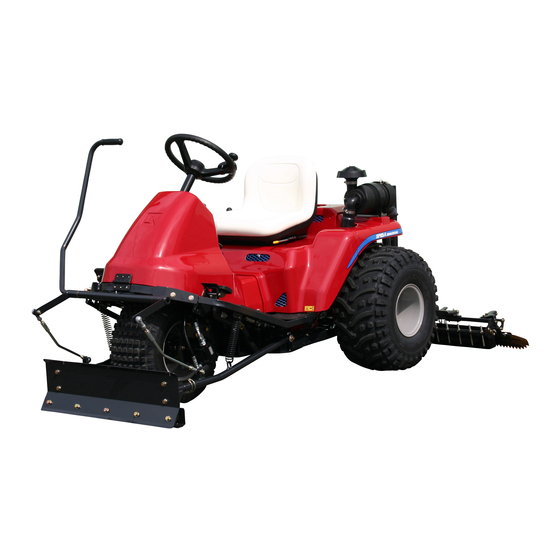
Bunker rake
Hide thumbs
Also See for SP05A:
- Owner's operating manual (79 pages) ,
- Owner's operating manual (80 pages) ,
- Owner's manual (89 pages)

Subscribe to Our Youtube Channel
Related Manuals for Baroness SP05A


Summary of Contents for Baroness SP05A
- Page 1 Bunker Rake Owner's Operating Manual Serial No. SP05A:20991- "Required reading" Read this manual before using the machine. Original Instructions Ver.1.6...
- Page 2 SP05A Greeting Thank you for purchasing the Baroness product. This manual describes the proper handling, adjustment, and inspection of your product. We hope you will use the product safely, and take advantage of its best performance. Keeping The Owner's Operating...
- Page 3 The operator is responsible for operating the product properly and safely. Maintenance should only be performed by a certified specialist. If you have any questions concerning maintenance or genuine parts, please contact a Baroness dealer or Kyoeisha. When making inquiries about the product, please specify the product's model designation and serial number.
- Page 4 When replacing parts, be sure to use genuine Baroness parts or parts designated by Kyoeisha. Note that the Baroness product warranty may not apply to defects caused by the use of parts from other companies. Prior to use, carefully read the following manuals to thoroughly understand the contents for safe and correct operation.
-
Page 5: Table Of Contents
SP05A Contents Safety .............. Page 1-1 Safe Operating Practices .......Page 1-2 Disposal ............Page 2-1 Recycle and Waste Disposal ......Page 2-2 Product Overview .......... Page 3-1 Specifications ..........Page 3-2 Names of Each Section ......... Page 3-4 Regulation Decals ..........Page 3-4 Safety Signs and Instruction Signs .... - Page 6 SP05A Contents...
-
Page 7: Safety
SP05A Safety Safe Operating Practices ...... Page 1-2 Training ..........Page 1-2 Preparation ..........Page 1-2 Operation ..........Page 1-3 Maintenance and Storage ..... Page 1-4 Page 1-1... -
Page 8: Safe Operating Practices
SP05A Safety Failure to adequately follow these safety Never allow children or people unfamiliar precautions may cause an accident resulting in with these instructions to use or service the injury or death. machine. Local regulations may restrict the age of the... - Page 9 SP05A Safety If fuel is spilled, do not attempt to start the Use extra care while operating machine with engine but move the machine away from a grass catcher or other attachments. the area of spillage and avoid creating any They can affect the stability of the machine.
- Page 10 SP05A Safety When transporting the machine on a truck or Use jack stands to support components a trailer, set the parking brake, stop the when required. engine, and fasten the machine to the truck Carefully release pressure from components with a rope or other suitable restraining with stored energy.
-
Page 11: Disposal
SP05A Disposal Recycle and Waste Disposal ....Page 2-2 About Recycle ........Page 2-2 About Waste Disposal ......Page 2-2 Page 2-1... -
Page 12: Recycle And Waste Disposal
SP05A Disposal Recycle and Waste Disposal About Recycle Recycling battery etc. is recommended for environmental conservation and economical use of resources. It may be required by local laws. About Waste Disposal Make sure that waste generated when servicing or repairing the machine is disposed of in accordance with local regulations. -
Page 13: Product Overview
SP05A Product Overview Specifications ........Page 3-2 Specifications .........Page 3-2 Sound Pressure Level ......Page 3-3 Sound Power Level ....... Page 3-3 Vibration Level ........Page 3-3 Carbon Dioxide (CO2) Emissions Measurement .........Page 3-3 Names of Each Section ......Page 3-4 Regulation Decals ........Page 3-4... -
Page 14: Specifications
SP05A Product Overview Specifications Specifications Model SP05A (2WD) SP05A (3WD) with Rake 84.65 in 215 cm ← and Blade Total length with Blade 90.55 in 230 cm ← Dimensions Total width 74.80 in 190 cm ← Total height 47.24 in 120 cm ←... -
Page 15: Sound Pressure Level
SP05A Product Overview Engine plug PLUG, CHAMPION XC92YC ← The factory default maximum engine rpm is 3,000 rpm. Sound Pressure Level Sound Pressure Level This machine was confirmed to have a continuous A-weighted sound pressure level of 84 dB by measuring identical machines in accordance with the procedure specified in ISO5395-1:2013. -
Page 16: Names Of Each Section
SP05A Product Overview Names of Each Section Regulation Decals Positions of Regulation Decals quwxcl-172 Names of Each Section_001 quwxcl-249 Steering wheel Positions of Regulation Decals_001 Front cover Serial number plate Blade (option) Specification decal Front tire Year of manufacture decal... -
Page 17: Regulation Decals
SP05A Product Overview Description of Regulation Decals Battery Capacity Decal Serial Number Plate (For Europe) The battery capacity decal indicates the The serial number plate indicates the model capacity by 20HR and CCA. and serial number of the machine. 2z2dxu-001... -
Page 18: Safety Signs And Instruction Signs
Part numbers for decals that need to be replaced are listed in the parts catalog. Warning Order them from a Baroness dealer or Kyoeisha. Apply the parking brake, stop the engine, remove the ignition key, and then leave the Positions of Safety Decals and Instruction machine. - Page 19 SP05A Product Overview Caution to Getting Pinched Decal Lead-Free Gasoline Decal K4205001930 K4209001310 Decal, caution to getting pinched Decal, lead-free gasoline Use lead-free gasoline. Caution May pinch - There is a risk of being pinched. xmitt2-002 Lead-Free Gasoline Decal_001 Fire Prohibited Decal...
- Page 20 SP05A Product Overview Caution to Getting Entangled Decal Caution to Noise Decal K4205001910 K4205002090 Decal, caution to getting entangled Decal, caution to noise Warning Watch for rotating parts - Keep your hands away from the belts while the engine is running.
-
Page 21: Handling Instructions
SP05A Handling Instructions Inspections ..........Page 4-2 Cautions for when You Leave The Machine ..........Page 4-18 Rake ............Page 4-2 Positions of Operation Decals ..... Page 4-18 Blade ............Page 4-2 Description of Operation Decals ..Page 4-19 Cultivator ..........Page 4-3 Throttle Lever ........Page 4-21... -
Page 22: Inspections
SP05A Handling Instructions Inspections Inspect the machine according to the maintenance schedule so that you will be able to take advantage of its optimum performance for a long period of time. Rake Inspection of Rake Due to frequent use or damage caused during... -
Page 23: Cultivator
SP05A Handling Instructions Cultivator Oil Cooler Inspection of Cultivator Inspection of Oil Cooler Note: Make sure that there is no damage to the Depending on the specifications, this function oil cooler. may not be available. Make sure that the oil cooler is not Due to frequent use or damage caused during contaminated. -
Page 24: Hydraulic Oil
SP05A Handling Instructions Remove the bolts, and then remove the Hydraulic Oil cover. Inspection of Hydraulic Oil Raise the rake and maintain that position on a level surface. Make sure that the oil level is at the middle of the oil gauge. -
Page 25: Hydraulic Hoses
SP05A Handling Instructions Hydraulic Hoses Outer element Inner element Inspection of Hydraulic Hoses Clip Cover Warning Air cleaner body When checking the hydraulic circuit for Cleaning of Air Cleaner pinhole leaks or oil leakage from nozzles, do not use your hands. Use items such as paper... -
Page 26: Battery
SP05A Handling Instructions Supply of Battery Fluid Outer element Inner element Danger Danger Clip Cover Be careful not to let your skin, eyes or clothes, Air cleaner body etc., come into contact with the battery fluid or accidentally swallow the fluid. -
Page 27: Tire
SP05A Handling Instructions Tire Wire Inspection of Tires Inspection of Wire Check the pneumatic pressure of the tires. Make sure that the wire is not cracked or damaged. Make sure that there are no cracks, damage or abnormal wear. If the wire is cracked or damaged, replace it with a new one immediately. -
Page 28: Engine Oil
SP05A Handling Instructions Engine Oil Supply of Engine Oil Inspection of Engine Oil Important Do not fill too much engine oil. Otherwise, the Important engine may be damaged. Securely tighten the oil level gauge and oil filler cap. Important Stop the engine, wait for 10 to 20 minutes Do not mix different types of engine oil. -
Page 29: Fuel
SP05A Handling Instructions It will take a while for the supplied engine oil Warning to descend into the oil pan. Check the oil level again 10 to 20 minutes Supply fuel after the engine is stopped and after supplying the oil. -
Page 30: Fuel Strainer
SP05A Handling Instructions Fuel Strainer Oil Leakage Inspection of Fuel Strainer Inspection of Oil Leakage The fuel strainer is installed near the fuel tank After approximately 50 hours of operation, and cleans the fuel that enters the carburetor. some joints may be loosened and oil and If the fuel flow is insufficient, clean or replace grease may leak. -
Page 31: Tightening Torques
SP05A Handling Instructions Tightening Torques Important Refer to the Tightening Torque table. Note that the Baroness product warranty may not apply to defects caused by incorrect or overtorque tightening, etc. Standard Tightening Torques Bolts and Nuts Important A number of bolts are used in each part of this machine. - Page 32 SP05A Handling Instructions General bolt Strength classification 4.8 Nominal diameter tib3yb-001 kgf-cm lb-in 3 - 5 30.59 - 50.99 26.55 - 44.26 7 - 9 71.38 - 91.77 61.96 - 79.66 14 - 19 142.76 - 193.74 123.91 - 168.17 29 - 38 295.71 - 387.49...
-
Page 33: Principal Tightening Torques
SP05A Handling Instructions Principal Tightening Torques Tightening Torque by Model SP05A Tighten the following bolts and nuts at the torque specified in the table. For thread locking adhesive, apply a middle strength thread locker (ThreeBond 1322 or equivalent anaerobic sealant). -
Page 34: Adjustment Before Work
SP05A Handling Instructions Adjustment of Seat Adjustment before Work Use the seat adjustment lever to adjust the Adjustment of Steering Wheel seat back and forth. Adjust the position according to the operator's Warning body size. Since it is dangerous, do not adjust the The adjustment lever is located beneath the steering wheel while traveling. -
Page 35: Adjustment Of Speed Adjustment Plate
SP05A Handling Instructions Adjust the fork prong bar to a position Adjustment of Speed Adjustment Plate where the rake load is applied to the wooden board and the tip of the fork prong Warning bar lightly touches the ground, and then lock it in place with the nut. -
Page 36: Adjustment Of Blade
SP05A Handling Instructions Adjustment of Blade Adjustment of Finishing Brush Note: Note: Depending on the specifications, this function Depending on the specifications, this function may not be available. may not be available. The blade can be adjusted with the bolt. -
Page 37: Procedure To Start/Stop Engine
SP05A Handling Instructions When used for normal finishing, adjust to the Caution position third from the bottom. Make sure that the covers are correctly in place and are not damaged. Important Starter operation must take 15 seconds or less. If the engine does not start, stop using the battery for 30 to 60 seconds to avoid exhausting the battery. -
Page 38: Operation Method
SP05A Handling Instructions Remove the ignition key. Positions of Operation Decals Leave the driver's seat. Close the fuel cock. The fuel cock is located near the fuel tank. Safety Mechanisms This machine features a safety device for starting/stopping the engine. -
Page 39: Description Of Operation Decals
SP05A Handling Instructions Rake Up/Down Mark Key switch mark Engine rotation decal Rake up/down mark Rake up/down mark This indicates up/down of the rake. Tilt steering mark Parking brake mark Light switch mark BRAKE decal FORWARD decal BACKWARD decal 2WD/3WD selector lever mark... - Page 40 SP05A Handling Instructions Parking Brake Mark BRAKE Decal Parking brake mark K4203001450 This indicates lock/release of the parking Decal, BRAKE brake. This indicates brake. BRAKE kgtxi7-004 7elqr2-001 Parking Brake Mark_001 BRAKE Decal_001 FORWARD Decal Lock Release K4203001430 Decal, FORWARD Light Switch Mark This indicates forward travel.
-
Page 41: Throttle Lever
SP05A Handling Instructions Choke Lever 2WD/3WD Selector Lever Mark Note: The choke lever is located on the left side Depending on the specifications, this function below the steering wheel and its knob is to be may not be available. pulled when starting the engine. -
Page 42: 2Wd/3Wd Selector Lever
SP05A Handling Instructions Up/down switch lever Caution The lights provide auxiliary lighting. DOWN Do not travel or operate the machine at night or under poor visibility. 2WD/3WD Selector Lever The light switch is located in the operation Note: panel. Depending on the specifications, this function may not be available. -
Page 43: Brake Pedal
SP05A Handling Instructions Brake Pedal Caution When leaving the driver's seat, park the machine on a stable, flat surface and be sure to apply the parking brake. Caution Do not park on a slope. dmhzyz-004 Front Cover_001 The brake pedal is located in the left foot area. -
Page 44: Rear Cover
SP05A Handling Instructions Rear Cover Rear cover Gas spring Warning When closing the rear cover, slowly lower it Stop the engine when performing while firmly supporting it, and then engage recommended maintenance operations that the cover fastener. do not require the engine to start when the rear cover is opened. -
Page 45: Instruments
SP05A Handling Instructions Cargo Box Instruments Note: Instruments on The Operation Panel Depending on the specifications, this function may not be available. Important The maximum loading weight is 15 ㎏ (33.07 lb). Cargo Box is a container to transport equipments such as a back pack blower which may be used together during cutting work. -
Page 46: Travel Of Machine
SP05A Handling Instructions (#21009 -) Important The number in red figures on a white background is incremented every thirty-six Before restarting the engine, be sure to close seconds. the unload valve. The number in white figures on a black background is incremented every hour. -
Page 47: Operations
SP05A Handling Instructions Operations Piston pump Unload valve operating pins Rake Bolt Lock nut Warning Important Do NOT start to move or stop the machine abruptly. When pushing in the unload valve operating pins, be careful about overtightening the bolts. -
Page 48: Blade
SP05A Handling Instructions Caution Caution Do not enter or leave a bunker via a steep If the blade is raised, do not touch the lifting slope or extremely uneven ground. lever. Important Caution When switching between 2WD and 3WD When getting on and off the machine, watch... -
Page 49: Cultivator
SP05A Handling Instructions Important Caution Perform blade operations in 2WD. Before starting operations, check that the area where the operations are to be performed is Shift the 2WD/3WD selector lever to the safe. "2WD" position to operate in rear-wheel 2WD. -
Page 50: Finishing Brush
SP05A Handling Instructions At the bunker area where the operation is to Caution be started, squeeze the clutch lever and pull the cultivator lever toward you. Before starting operations, check that the area where the operations are to be performed is safe. -
Page 51: Transporting
SP05A Handling Instructions At the bunker area where the operation is to be stopped, shift the up/down switch lever to the "UP" position to raise the rake. The finishing brush is raised at the same time. Leave the bunker. If tire tracks remain, use the broom to remove them. - Page 52 SP05A Handling Instructions Page 4-32 Storage...
-
Page 53: Maintenance
SP05A Maintenance Maintenance Precautions ..... Page 5-2 Maintenance Schedule ......Page 5-2 Adjusted Values ........Page 5-3 Jacking Up The Machine .......Page 5-4 About Jacking Up The Machine .....Page 5-4 Jack-Up Points ........Page 5-4 Greasing ..........Page 5-5 About Greasing ........Page 5-5 Greasing Points ........ -
Page 54: Maintenance Precautions
Use tools appropriate for each maintenance operation. Important For the safe and best performance of your machine, use Baroness genuine parts for replacement and accessories. Please note that our product warranty may be void if you use non-genuine parts for replacement or accessories. -
Page 55: Adjusted Values
SP05A Maintenance Maintenance Item Remarks Steering chain ○ Greasing, oiling ○ ... -
Page 56: Jacking Up The Machine
SP05A Maintenance Jack-Up Points Jacking Up The Machine About Jacking Up The Machine Warning When replacing a tire or beginning any other maintenance or repairs, be sure to chock the wheels to prevent the machine from moving. Before jacking up the machine, park it on a... -
Page 57: Greasing
SP05A Maintenance Front left frame Greasing Important About Greasing One nut is used to install the reinforcing plate. Since there may be adhesion or damage due Be careful that the jack does not hit the nut. to lack of grease on moving parts, they must be greased. -
Page 58: Greasing Points
SP05A Maintenance Traveling pedal fulcrum Greasing Points Grease nipples are installed in the following locations. Add grease every 50 hours of operation. 8bq62b-002 Greasing Points_002 Brake pedal fulcrum 8bq62b-458 Greasing Points_001 No. of 8bq62b-003 Greasing Location Points Greasing Points_003... - Page 59 SP05A Maintenance Pump neutral lever fulcrum (above piston pump) 8bq62b-008 Greasing Points_008 8bq62b-005 Blade lever fulcrum Greasing Points_005 Front wheel shaft rhombic flange unit 8bq62b-006 8bq62b-009 Greasing Points_006 Greasing Points_009 Rear wheel brake lever fulcrum Blade arm fulcrum 8bq62b-010 Greasing Points_010...
-
Page 60: Lubrication
SP05A Maintenance Rake mount No. of lubrica Location ting points Rake up/down cylinder spherical bearing Rake up/down cylinder spherical bearing There is one point. 8bq62b-459 Greasing Points_011 Rake fulcrum 8bq62b-462 Lubricating Points_002 Maintenance Work Change of Fork Prong Bar... -
Page 61: Change Of Small Blade
SP05A Maintenance Change of Small Blade Note: Depending on the specifications, this function may not be available. When wear of the small blade causes a reduction in the amount of sand that is lifted up, replace the small blade. Loosen the bolts installing the small blade, and then replace the small blade. -
Page 62: Change Of Finishing Brush
SP05A Maintenance Tighten the bolts for the trapezoidal cultivator Remove the bolts, and then replace the fitting. finishing brush. Caution When installing the cultivator, pay attention to its falling. Install the cultivator to the machine with bolts. Change of Finishing Brush... - Page 63 SP05A Maintenance 2WD specifications 3WD specifications Rhombic flange unit Bolt A Spring washer A Washer A Bolt B Nut B Spring washer B Washer B Front wheel bracket Front wheel arm Bolt C Wheel mounting bolt Spring washer C Washer C...
-
Page 64: Adjustment Of Belt Tension
SP05A Maintenance Remove the bolts. High nut Remove the tire from the wheel mounting Spring cover seat. Tension fulcrum fitting Important Belt Tighten the bolts in the tightening order Spring (crosswise). Tension pulley For installing the rear tires, reverse the Engine pulley removing procedure. -
Page 65: Adjustment Of Brake
SP05A Maintenance Adjustment of Brake Brake pedal Spring rod Caution Adjustment bolt Make sure that the brake wire is not cracked Brake wire or damaged. Brake lever Rear wheel Caution Adjustment of Spring Rod If the brake is not sufficiently effective, adjust the brake wire. -
Page 66: Adjusting The Neutral Position Of The Piston Pump
SP05A Maintenance Slowly turn the camshaft until the rear wheel Adjusting The Neutral Position of The stops, and then use the nut to lock the Piston Pump camshaft at the stopped position. If the machine moves forward or backward while the traveling pedals are released, they are not set to the neutral position. -
Page 67: Change Of Hydraulic Oil
SP05A Maintenance Remove the drain plug of the hydraulic Push-pull cable tank, and then drain the old oil into a Lock nuts container. Connection point on pedal Wind new sealing tape on the drain plug, and then attach it to the hydraulic tank. -
Page 68: Change Of Hydraulic Oil Filter
SP05A Maintenance Make sure that there is no oil leakage at the Change of Hydraulic Oil Filter sealing surface of the filter cartridge. Check the hydraulic oil level. Caution If it is low, supply hydraulic oil until it reaches Be careful with hot oil, which could cause the specified level. -
Page 69: Change Of Engine Oil
SP05A Maintenance Remove the oil filler cap, and then supply Change of Engine Oil new engine oil until the oil reaches a level in between the upper and lower limit lines on Caution the oil level gauge. Be careful with hot oil, which could cause Supply 1.0 dm... -
Page 70: Change Of Engine Oil Filter
SP05A Maintenance Supply engine oil until it reaches the Change of Engine Oil Filter specified level. "Supply of Engine Oil" (Page 4-8) Caution Start the engine, and then stop it after 10 to Be careful with hot oil, which could cause 20 minutes. -
Page 71: Change Of Fuse
SP05A Maintenance Change of Fuse Fuses Important When performing maintenance on the electrical system, be sure to remove the negative battery wire. Important If a fuse blows, a short may have occurred within the electrical circuit. Check for the cause, such as faulty terminal connections, damaged wiring or terminals, or incorrect wiring. - Page 72 SP05A Maintenance Page 5-20 Maintenance Work...
- Page 76 1-26, Miyuki-cho, Toyokawa-city, Tel : +81 - 533 - 84 - 1390 Head Office Fax : +81 - 533 - 84 - 1220 Aichi-pref, 442-8530 JAPAN SP05A---UM--GBZ/21A-00-S.K E01a[SP05A_EU01a]...
Need help?
Do you have a question about the SP05A and is the answer not in the manual?
Questions and answers