Table of Contents
Advertisement
Available languages
Available languages
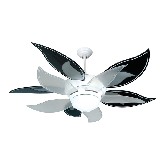
Bloom
Installation Guide
For Model:
BL52-LED
E192641
net weight of fan: 30.64 lb (13.9 kg)
READ THESE INSTRUCTIONS AND
SAVE THEM FOR FUTURE USE
Table of Contents:
Safety Tips. pg. 2
Unpacking Your Fan. pg. 3
Parts Inventory. pg. 3
Installation Preparation. pg. 4
Hanging Bracket Installation. pg. 4
Blade Assembly, Large Blades. pg. 5
Fan Assembly. pgs. 5 - 6
Wiring. pg. 7
Canopy Assembly. pg. 8
Blade Assembly, Small Blades. pg. 8
Light Kit Assembly. pg. 9
Control. pgs. 9 - 10
Remote Control Operation. pg. 11
Testing Your Fan. pg. 11
Troubleshooting. pg. 12
Warranty. pg. 12
Parts Replacement. pg. 12
page 1
PRINTED IN CHINA
Advertisement
Table of Contents

Subscribe to Our Youtube Channel
Related Manuals for Craftmade Bloom


Summary of Contents for Craftmade Bloom
-
Page 1: Table Of Contents
READ THESE INSTRUCTIONS AND SAVE THEM FOR FUTURE USE Bloom Installation Guide For Model: Table of Contents: BL52-LED Safety Tips. pg. 2 Unpacking Your Fan. pg. 3 Parts Inventory. pg. 3 Installation Preparation. pg. 4 Hanging Bracket Installation. pg. 4 Blade Assembly, Large Blades. -
Page 2: Safety Tips
SAFETY TIPS. WARNING: To reduce the risk of electrical shock, turn off the electricity to the fan at the main fuse box or circuit panel before you begin the fan installation or before servicing the fan or installing accessories. READ ALL INSTRUCTIONS AND SAFETY INFORMATION CAREFULLY BEFORE INSTALLING YOUR FAN AND SAVE THESE INSTRUCTIONS. -
Page 3: Unpacking Your Fan
1. Unpacking Your Fan. Carefully open the packaging. Remove items from Styrofoam inserts. Remove motor housing and place on carpet or Styrofoam to avoid damage to finish. Do not discard fan carton or Styrofoam inserts should this fan need to be returned for repairs. -
Page 4: Installation Preparation
3. Installation Preparation. blade edge To prevent personal injury and damage, ensure inches 7 feet (76cm) that the hanging location allows the blades a (2.13m) clearance of 7 feet (2.13m) from the floor and 30in. (76cm) from any wall or obstruction. 12ft. -
Page 5: Blade Assembly, Large Blades
5. Blade Assembly, Large Blades. NOTE: Only the large blades will be installed at this time; screws and the small blades will be installed later on. lock washers Remove screws and lock washers from yoke plate (located in top plate at top of motor housing). Lift yoke yoke plate plate and top plate to remove from motor housing and set aside. - Page 6 6. Fan Assembly. (cont.) downrod Locate canopy cover in hardware pack. Slide yoke cover, canopy cover and canopy over downrod. [Refer to diagram 3.] (Note: Canopy cover must be canopy turned with shiny side toward the motor housing.) canopy cover Thread safety cable and wires through hanging ball yoke and then slide hanging ball over downrod--the top...
-
Page 7: Wiring
7. Wiring. Modifications not approved by the party responsible for compliance WARNING: Turn off circuit breakers to current fixture could void the user's authority to operate the equipment. from breaker panel and be sure switch is turned to the *NOTE: This equipment has been tested and found to comply with the limits for a Class B digital device, pursuant to Part 15 of the FCC Rules. -
Page 8: Canopy Assembly
8. Canopy Assembly. hanging bracket Locate 2 screws on underside of hanging bracket and remove screw closest to the open end of the hanging bracket. Partially loosen the other screw. Lift canopy to hanging bracket. Place rounded part of slotted hole in canopy screw over loosened screw in hanging bracket and canopy... -
Page 9: Light Kit Assembly
10. Light Kit Assembly. Remove 1 screw from motor plate (on underside of motor housing) and partially loosen the other 2 screws. Connect WHITE wire from motor housing to WHITE wire from LED light kit. Connect BLACK (or BLUE) wire from motor housing to BLACK wire from LED light kit. -
Page 10: Assembly Of Handheld Remote
11. Assembly of Handheld Remote Control. (cont.) Attach black faceplate to front of wall control; press down firmly. [Refer to diagram 3.] post post hole hole Align holes in wall control with posts located on inside of TOP part of remote control cover and press together firmly. -
Page 11: Remote Control Operation
13. Remote Control Operation. ON/OFF slider switch - turns wall control ON or OFF (switch not functional on handheld remote) HIGH button - turns fan to HIGH speed MED button - turns fan to MEDIUM speed LOW button - turns fan to LOW speed OFF button - turns fan OFF L1 button - turns light kit ON/OFF when pressed once;... -
Page 12: Troubleshooting
Service at 1-800-486-4892 to arrange for return of fan. 1. Check wall switch to fan/wall control. Return fan, shipping prepaid, to Craftmade. We will repair 2. Check to be sure wall control (optional use) is wired or ship you a replacement fan, and we will pay the return properly. - Page 13 LEER ESTAS INSTRUCCIONES Y GUARDARLAS PARA UTILIZACIÓN FUTURA Bloom Guía de instalación Para modelo: BL52-LED Índice de materias: Sugerencias de seguridad. Pág. 2 Desempaquetado del ventilador. Pág. 3 Inventario de piezas. Pág. 3 Preparación para la instalación. Pág. 4 Instalación del soporte de montaje. Pág. 4 Colocación de las aspas, aspas grandes.
- Page 14 SUGERENCIAS DE SEGURIDAD. ADVERTENCIA: Para evitar la posibilidad de una descarga eléctrica, desconectar la corriente en la caja de fusibles principal o el interruptor protector antes de iniciar la instalación del ventilador o antes de repararlo o instalar accesorios. LEER TODAS LAS INSTRUCCIONES E INFORMACIÓN DE SEGURIDAD CUIDADOSAMENTE ANTES DE INSTALAR SU VENTILADOR Y GUARDAR ESTAS INSTRUCCIONES.
- Page 15 1. Desempaquetado del ventilador. Abrir el empaque cuidadosamente. Sacar los artículos del embalaje. Sacar el motor y ponerlo en una alfombra o en el embalaje para evitar rayar el acabado. Guardar la caja de cartón o el empaquetamiento original en caso de que tenga que mandar el ventilador para alguna reparación.
- Page 16 3. Preparación para la instalación. borde del aspa Para prevenir daño corporal y otros daños, estar seguro de que el lugar en donde va a colgar el 76cm ventilador le permite un espacio libre de 2,13m 2,13m pulg.) (7 pies) entre las puntas de las aspas y el piso y (7 pies) 76cm (30 pulg) entre las aspas y cualquier pared u otra obstrucción.
- Page 17 5. Colocación de las aspas, aspas grandes. NOTA: Por ahora sólo se instalarán las aspas grandes; las aspas tornillos y pequeñas se instalarán más adelante. arandelas de seguridad Sacar los tornillos y arandelas de seguridad de la placa del cuello (localizada en la placa superior del bastidor del motor). Levantar la placa del cuello y la placa superior para quitarlas placa del cuello del bastidor del motor y dejarlas a un lado.
- Page 18 6. Ensamblaje del ventilador. (cont.) tubo Localizar la tapa de la cubierta decorativa en un paquete de artículos de ferretería. Deslizar la cubierta del cuello, la tapa de la cubierta decorativa y la cubierta decorativa por cubierta el tubo. [Referirse al diagrama 3.] (Nota: Se tiene que voltear decorativa la tapa de la cubierta decorativa para que el lado brillante tapa de la...
- Page 19 7. Instalación eléctrica. Las modificaciones no aprobadas por la parte responsable de la conformidad podrían invalidar la autorización del usuario para manejar el equipo. ADVERTENCIA: Apagar los cortacircuitos en el panel de *NOTA: Se han hecho pruebas en este equipo y se ha comprobado que cumple con los límites para un electricidad que suplen corriente a la caja de salida y aparato digital de clase B, de acuerdo con la Parte 15 de las Reglas de la FCC.
- Page 20 8. Colocación de la cubierta decorativa. Localizar los 2 tornillos en la parte inferior del soporte de montaje y quitar el tornillo que esté soporte localizado más cerca del extremo abierto del de montaje soporte de montaje. Aflojar parcialmente el otro tornillo.
- Page 21 10. Instalación del juego de luz. Quitar 1 tornillo de la placa del motor (en el lado inferior del bastidor del motor) y aflojar los otros 2 tornillos. Conectar el cable BLANCO del bastidor del motor al cable BLANCO del juego de luz LED. Conectar el cable NEGRO (o AZUL) del bastidor del motor al cable placa del motor NEGRO del juego de luz LED.
- Page 22 11. Ensamblaje del control remoto de mano. (cont.) Fijar la tapa negra a la parte delantera del control de pared; apretar la tapa fijamente. [Referirse al agujero poste agujero diagrama 3.] para el poste Alinear los agujeros en el control de pared con los postes que se encuentran adentro de la parte SUPERIOR de la cubierta del control remoto y apretar fijamente.
- Page 23 13. Funcionamiento del control remoto. Interruptor corredero ON/OFF - ENCIENDE y APAGA el control de pared ON/OFF(el interruptor no funciona en el control de mano) Botón HIGH - pone el ventilador en velocidad ALTA Botón MED - pone el ventilador en velocidad MEDIA Botón LOW - pone el ventilador en velocidad BAJA Botón OFF - APAGA el ventilador Botón L1 - ENCIENDE/APAGA el juego de luz cuando se...
- Page 24 Craftmade. Nosotros repararemos el batería. motor al comprador o le enviaremos uno de reemplazo y Craftmade pagará los gastos de envío de regreso. Problema: El juego de luz no se ilumina. GARANTÍA LIMITADA DE 6 AÑOS hasta DE POR VIDA: Soluciones: CRAFTMADE reparará...
Need help?
Do you have a question about the Bloom and is the answer not in the manual?
Questions and answers