Advertisement

Ope�ato�'s �anual:
It is the owne�'s �esponsibility to ensu�e that all ope�ato�s
of this �a�hine ha�e �ead and unde�stand the �ontent of this �anual befo�e using
the p�odu�t! Ca�eless o� i�p�ope� use of this �a�hine �an �ause se�ious o� e�en
fatal inju�y! Allow only �o�petent adults to ope�ate this �a�hine!
Manual del ope�ado�
Lea �uidadosa�ente estas inst�u��iones y asegú�ese
de que las �o�p�ende bien antes de usa� el ��� ���� ��
Manuel d'utilisation
�euille�� li�e attenti�e�ent �es inst�u�tions et assu�e����ous de
bien les �o�p�end�e a�ant d'utilise� la �a�hine �odèle ��� ���� ��
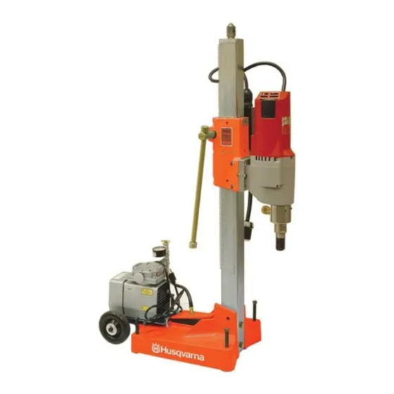
DS 700
DS 800
��� ���� ��


Advertisement

Table of Contents
loading

Summary of Contents for Husqvarna DS 700

  • Page 1 �a�hine ha�e �ead and unde�stand the �ontent of this �anual befo�e using the p�odu�t! Ca�eless o� i�p�ope� use of this �a�hine �an �ause se�ious o� e�en fatal inju�y! Allow only �o�petent adults to ope�ate this �a�hine! DS 700 Manual del ope�ado� Lea �uidadosa�ente estas inst�u��iones y asegú�ese DS 800 de que las �o�p�ende bien antes de usa�...
  • Page 2: Table Of Contents

    Thank you for purchasing your new machine from fatal injury! Allow only competent adults to Husqvarna Construction Products. We have provided operate this machine! important safety messages in this manual and on the ma- chine.
  • Page 3: Symbols And Decals

    SYMBOL DEFINITIONS • Please read the instructions for use prior to operating the machine for the first time. • Mandatory • Obligatorio • Indication • Indicación • Prohibition • Prohibición • Warning Triangle • Triángwulo De Advertencia • Wear Eye Protection •...
  • Page 4 SYMBOL DEFINITIONS • Use In Well Ventilated Area • Usar En Una Área Bien Ventilada • Do Not Use In Flammable Areas • No Usar In Áreas Inflamables • Machinery Hazard, Keep Hands And Feet Clear. • Máquina Peligrosa - Mantenga Manos Y Pies Alejados De La Máquina •...
  • Page 5 DECAL, WARNING LOCATION: TOP OF BASE P/N 542 17 45-45 DECAL, HUSQVARNA DS 800 DECAL, HUSQVARNA DS 700 LOCATION: SIDES OF BASE (2X, DS 800) LOCATION: SIDES OF BASE (2X, DS 700) P/N 502 46 43-01 P/N 502 45 42-01...
  • Page 6: Safety Instructions

    SAFETY INSTRUCTIONS General Safety: The working area must be completely clear, well lit and all safety hazards WARNING! removed. Before operating machine, read and un- derstand this entire operation manual & Do not use machine in flammable area. operation manual supplied with the power source.
  • Page 7 Your tool must be plugged into an ap- Fig. B propriate outlet, properly installed and grounded in accordance with all codes and ordinances. The plug and outlet should look like those in Fig- SAFETY INSTRUCTIONS ures A and B. Double Insulated Tools: Electrical Safety: Tools with Two Prong Plugs Grounded Tools MUST...
  • Page 8 SAFETY INSTRUCTIONS SAFETY FIRST! WARNINGS DO’s AND DO NOT’s WARNING: FAILURE TO COMPLY WITH THESE WARNINGS AND OPERATING INSTRUCTIONS COULD RESULT IN DEATH OR SERIOUS BODILY INJURY. DO read this entire operator’s manual before operating this machine. Understand all warnings, instructions, and controls.
  • Page 9 If you have any questions relative to its application, DO NOT use the machine until you have written Husqvarna Construction Products, Inc. and we have advised you. Husqvarna Construction Products, Inc.
  • Page 10: Parts Identification (What Is What)

    Angle Bracket Accessory (Column to Base) Crank Handle / Pinion DS 800 Only (Not Shown) Wear Plate Adjustment Screws Angle Bracket Assembly - DS 700 / DS 800 Jack Screw (Not Shown) Gear Rack Anchor Bolt & Washer (Not Included) Leveling Screws (4) Anchor Bolt Mounting Slot &...
  • Page 11: Features

    DS 800: 2-7/8 x 2-7/8 inch (73 x 73mm) Width x Depth x advice for your safety 42” (1067mm) Height. Before leaving our factory every machine is Overall Dimensions (Length x Width x Height): thoroughly tested. DS 700 / DS 800: 27-1/2” L x 14” W x 44-1/2” H (698 x 356 x 1130mm). Follow our instructions strictly and your machine will give you long service in normal operating con- Weight: ditions.
  • Page 12: Machine Set-Up

    MACHINE SET-UP WARNING! Machine must be held securely to prevent injury to operator or damage to machine! Always anchor machine properly before drilling! Anchors shall only be used if the material being drilled has the mechanical strength required to hold the anchor. DO NOT use vacuum system to secure machine to a wall (horizontal drilling) or a ceiling! Use ONLY anchor bolts to secure the machine to a...
  • Page 13 MACHINE SET-UP • When configured to use an Anchor Bolt & Washer (U), the Vacuum System will not be used, the “slot cap” must be removed from the Anchor Bolt Slot (V), and the four Leveling Bolts (F) shall be adjusted so that the gasket will not contact the mounting surface.
  • Page 14 The addition of this accessory will allow the drill stand to tilt backwards (toward wheels) at up to a 45 degree angle. Use the DS 700 / DS 800 spare parts list to de- termine the correct part number for this accessory.
  • Page 15 (W) Required • Attach Control Panel (Y) to Carriage (K) at the “slip-on” 1”-10” (25 - 254mm) spade connection. See “Control Panel (Y) Parts & DS 700 Electrical Connections” diagram at right. 12-14” (305 - 356mm) 1”-14” (25 - 356mm) •...
  • Page 16 20 - 48 inch (508 - 1219mm) ** 20gpm@2000psi 175 - 350 RPM (High) ** 9 - 20 inch (229 - 508mm) ** (76 L/min@138 bar) Husqvarna DM 506 H 2M 2-Speed** 150 - 300 RPM (Low) ** 10 - 20 inch (254 - 508mm) ** 2-Speed...
  • Page 17: Diamond Core Bit Installation

    Motor Mfg Spindle Thread Pitch Milwaukee 1-1/4”-7UNC Cardi 1-1/4”-7UNC Husqvarna 1-1/4”-7UNC (Hydraulic) • A separating washer, or other device, should be CORE BIT REMOVAL AIDS installed between the bit and the shoulder of the Separating Washers &...
  • Page 18: Operation

    OPERATION WARNING! Before operating machine, read and understand this entire operation manual & operation manual supplied with the power source. Be familiar with machine before opera- tion! WARNING! Always disconnect the power source (electrical or hydraulic) prior to installing the bit. Electrical Power Switches MUST be in OFF posi- tion before connecting machine to electrical power source!
  • Page 19 OPERATION WARNING! DO NOT contact rotating parts while motor is ON, or machine is in operation! • After vacuum pressure is verified, machine is securely held in place, all unauthorized persons are out of the area, and operator is clear of rotating, turn Drill Motor Switch (Z) to ON position.
  • Page 20 OPERATION Anchored Machines (Non-Vacuum): • Verify that Control Panel Electrical Power Switches (Z & AA) are in the OFF position! • Verify that Core Drill is positioned properly on a flat surface, and is securely anchored in position. • Connect Male Plug Pigtail (FF) on Control Panel to the Female Receptacle of a extension cord (not supplied).
  • Page 21: Maintenance

    MAINTENANCE CLEANING VACUUM PUMP FILTER: Any persons not involved in the work, Periodic cleaning of the Vacuum Pump Filter / Water should leave the area. Trap (O) may be required. • Unscrew filter bowl from filter head. The working area must be completely •...
  • Page 22: Trouble Shooting

    TROUBLE SHOOTING RETRIEVING CORES & DEEP DRILLING: DIAMOND CORE DRILLING VARIABLES: Below are some factors that influence diamond core WARNING! performance. When coring through floors, cores may drop from • Amount of Water. bit. Provide proper protection for people / prop- •...
  • Page 23: Accessories

    17400 West 119th Street, Olathe, Kansas 66061 USA Corporate Office: 913-928-1000 Corp. Office Fax: 913-438-7951 www.husqvarnacp.com For local service, please contact your local Husqvarna Construction Products representative. Europa / Europe: Husqvarna Construction Products SE-433 81 Partille, Sweden Tel: +46 31 94 90 00, Fax: +46 31 94 90 50...
  • Page 24 504 80 58-01 2��7�32...

This manual is also suitable for:

Ds 800

Table of Contents