Table of Contents
Advertisement
Quick Links
Advertisement
Table of Contents

Related Manuals for Husqvarna DM 330


Summary of Contents for Husqvarna DM 330
- Page 1 Workshop manual DM 330, DM 340 HUSQVARNA CONSTRUCTION PRODUCTS...
-
Page 2: Table Of Contents
CONTENTS Page HUSQVARNA PRESENTATION – DM 330, DM 340 2. LITERATURE DM 330 COMPONENTS, WORK TIPS 4. BASIC STRUCTURE DM 340 5. GEAR HOUSING – PRIMARY SHAFT 6. SLIP CLUTCH 7. GEAR HOUSING – INTERMEDIATE SHAFT 8. GEAR HOUSING – SPINDLE SHAFT 9. -
Page 3: Presentation - Dm 330, Dm 340
PRESENTATION – DM 330, DM 340 DM 330 – model versions DM 330 230 V or 120 V The electric motor is designed for 230 V (220–240 V) with 2700 W motor output and 120 V (100–130 V) with 2400 W motor output. -
Page 4: Literature
”Gear housing – intermediate shaft” (Example) Spares Spares DM330, DM340 The folders include all spares for Husqvarna DM330 and DM 340 The folder contains complete exploded drawings for the whole machine where the location, spares number and appearance of each component is easy to identify. -
Page 5: Components, Work Tips
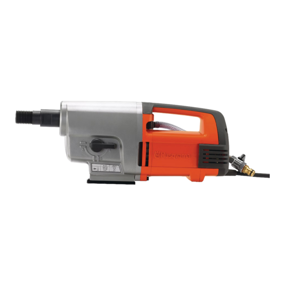
COMPONENTS, WORK TIPS Components 1. Drill spindle 8. SmartStart™ 2. Gear housing 9. Circuit breaker 3. Gear knob 10. Load indicator 4. Gear box cover 11. Mains cable 5. Leak hole (fault indicator) 12. Water connector with valve 6. Electric motor 13. -
Page 6: Basic Structure
BASIC STRUCTURE Basic modules The machine can be separated into three basic modules: 1. The gear housing with three gear selection positions. 2. The gear box cover which is the bearing carrier for the shafts in the gear housing and separates the oil-filled gear housing from the electric motor. - Page 7 BASIC STRUCTURE Oil change in gear housing You can change the oil when the motor has been removed from the gear housing. Turn the machine vertically with the motor facing up when dis - mantling. Oil change You must change the oil at 300 hour operational intervals. Drain and top up the oil through the hole in the motor shaft.
-
Page 8: Gear Housing - Primary Shaft
GEAR HOUSING – PRIMARY SHAFT Function The gear housing contains a transmission that reduces the high speed of the electric motor to a lower speed on the spindle shaft. Transmission is based on three shafts: primary shaft (A), intermediate shaft (B) and spindle shaft (C). The electric motor powers the top gear wheel on the primary shaft. -
Page 9: Slip Clutch
Tools For adjustment of the slip torque, two special tools are needed that are manufactured by Husqvarna along with a torque wrench. 531 12 31-22 Clamping ring with attachment for 1/2 inch ratchet/torque wrench. 522 91 40-01... -
Page 10: Gear Housing - Intermediate Shaft
GEAR HOUSING – INTERMEDIATE SHAFT Dismantling – intermediate shaft Gear selection position 2 Set the gear selector to position 2. Remove the circlip and lift up the gear drive Remove the circlip on the spindle shaft using circlip pliers. Lift out the gear drive. - Page 11 GEAR HOUSING – INTERMEDIATE SHAFT Remove the guide wedge Remove the lock ring A small pair of lock ring pliers is needed to remove the lock ring, manufacture: Milbar/Imperial IR-15R) or equivalent Start by turning the lock ring to ensure Milbar/Imperial the opening is accessible by pliers in the IR-15R...
-
Page 12: Gear Housing - Spindle Shaft
GEAR HOUSING – SPINDLE SHAFT Function The spindle shafts gear wheel is driven by the upper gear wheel of the inter - mediate shaft. At the upper storage point, water is supplied to the drill spindle. The transmission in this machine is rarely the cause of any problems. Incorrect handling of the machine could, however, cause the actual spindle shaft to bend, or damage the tool bracket. - Page 13 GEAR HOUSING – SPINDLE SHAFT Bearing replacement – spindle bearings Remove inner circlip When the spindle shaft has been removed from the gear housing, you can remove the bearing from the shaft. First remove the circlip. Pull the shaft out of the bearing The ball bearing is forced fitted onto the shaft.
-
Page 14: Gear Housing - Bearing Replacement
GEAR HOUSING – BEARING REPLACEMENT Tools Dismantling 1. Internal bearing extractor to grip behind the bearings. 2. Use a counter stay device where there is a counterhold. 3. A slide hammer is an alternative to the counter stay device if there is no counterhold available. Bearing replacement Dismantling needle bearings The gear box cover's two needle bearings are removed as... -
Page 15: Carbon Brushes
CARBON BRUSHES Replacing the carbon brushes The two carbon brushes transfer electric current to the motor's rotor. The carbon brushes are wear parts that must be checked regularly. Every week if the machine is used on a daily basis. You should replace the carbon brushes when around half is left. You can easily measure this using a slide gauge without removing the brushes. -
Page 16: Wiring Diagram, Cabling - 230 V
WIRING DIAGRAM, CABLING – 230 V Assembly diagram YELLOW BLACK The assembly diagram shows the colours and positions of the connection cables GREY Stator for the electrical connections. GREY Rotor BLACK GREY BLACK Stator GREY TRANSPARENT WHITE WHITE BLACK BLACK WHITE BLACK BROWN... -
Page 17: Wiring Diagram, Cabling - 120 V
WIRING DIAGRAM, CABLING – 120 V Assembly diagram YELLOW BLACK The assembly diagram shows the colours and positions of the connection cables GREY Stator for the electrical connections. GREY Rotor BLACK BLACK Stator BLACK BLACK BLACK BROWN Residual Current Device BLUE GREEN/YELLOW Component placement... -
Page 18: Rotor
Use a bearing puller or a small standard puller. The bearing puller can be acquired from Husqvarna, item no. 531 00 48-67. Rem: The wearing ring does not need removing unless the rotor is to be sepa - rated from the motor cover. - Page 19 ROTOR Bearing replacement Bearing replacement Dismantle the rotor. Dismantle the rotor as per the previous description. Collector side – bearing Collector side – bearing replacement replacement First remove the sensor. It has a First remove the magnetic speed sensor screw thread. in the middle of the shaft.
-
Page 20: Stator - 230 V
STATOR – 230 V Functional test Fractures to the stator winding are easiest to indicate using the check below. In general, short-circuited windings can also be identified, particularly if the short circuit eliminates current in several winding turns. If the short circuit only eliminates a few turns, the measurement is unlikely to record this. -
Page 21: Stator - 120 V
STATOR – 120 V Functional test Fractures to the stator winding are easiest to indicate using the check below. In general, short-circuited windings can also be identified, particularly if the short circuit eliminates current in several winding turns. If the short circuit only eliminates a few turns, the measurement is unlikely to record this. -
Page 22: Tools
TOOLS = Service operation ● The special tools below are needed for service work to The tools listed below are available from Husqvarna. DM330/DM340 but are not sold by Husqvarna. 531 12 31-22 Lock ring pliers Clamping ring Make: Milbar/Imperial IR-15R. - Page 23 www.husqvarnacp.com 525 59 31-26 English 2009-02...
Need help?
Do you have a question about the DM 330 and is the answer not in the manual?
Questions and answers