Table of Contents
Advertisement
Quick Links
Quick Guide
V8360W Series
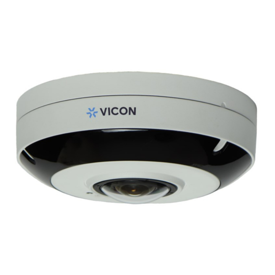
Network Panoramic Dome Cameras
XX314-20-00
Vicon Industries Inc. does not warrant that the functions contained in this equipment will
meet your requirements or that the operation will be entirely error free or perform precisely as
described in the documentation. This system has not been designed to be used in
life-critical situations and must not be used for this purpose.
Document Number: 8009-8314-20-00 Product specifications subject to change without notice.
Issued: 12/19 Copyright © 2019 Vicon Industries Inc. All rights reserved.
Vicon Industries Inc.
Tel: 631-952-2288) Fax: 631-951-2288
Toll Free: 800-645-9116
24-Hour Technical Support: 800-34-VICON
UK: 44/(0) 1489-566300
www.vicon-security.com
(800-348-4266)
Advertisement
Table of Contents

Summary of Contents for Vicon V8360W Series
- Page 1 Network Panoramic Dome Cameras XX314-20-00 Vicon Industries Inc. Vicon Industries Inc. does not warrant that the functions contained in this equipment will Tel: 631-952-2288) Fax: 631-951-2288 meet your requirements or that the operation will be entirely error free or perform precisely as Toll Free: 800-645-9116 described in the documentation.
-
Page 2: Explanation Of Graphical Symbols
WARNING TO REDUCE THE RISK OF FIRE OR ELECTRIC SHOCK, DO NOT EXPOSE THIS PRODUCT TO RAIN OR MOISTURE. DO NOT INSERT ANY METALLIC OBJECT THROUGH THE VENTILATION GRILLS OR OTHER OPENNINGS ON THE EQUIPMENT. CAUTION CAUTION RISK OF ELECTRIC SHOCK DO NOT OPEN WARNING: TO REDUCE THE RISK OF ELECTRIC SHOCK, DO NOT REMOVE COVER (OR BACK). -
Page 3: Fcc Compliance Statement
FCC COMPLIANCE STATEMENT This device complies with Part 15 of the FCC Rules. Operation is subject to the following two conditions: (1) this device may not cause harmful inter- ference, and (2) this device must accept any interference received, including interference that may cause undesired operation. -
Page 4: Important Safety Instructions
IMPORTANT SAFETY INSTRUCTIONS 1. Read these instructions. 2. Keep these instructions. 3. Heed all warnings. 4. Follow all instructions. 5. Do not use this apparatus near water. 6. Clean only with dry cloth. 7. Do not block any ventilation openings. Install in accordance with the manufacturer instructions. 8. - Page 5 1 Introduction The V8360W panoramic camera is a fisheye 360° IP dome camera that is state-of-the-art in visual quality and supports a suite of unique and impressive features. This 360-degree dome camera can be mounted on a ceiling or wall where it can truly make use of the incredible range of its fisheye lens to capture a wide view.
-
Page 6: Installation
2 Installation For the network camera to operate, it is necessary to connect a network cable for data transmission and power connection from a power adapter. Depending on operation methods, it is possible to connect an alarm cable. 2.1 Overview •... - Page 7 • Connectors Item Description 12 VDC 12 VDC Power input (2-pin terminal block) Ethernet, RJ-45 port compatible RJ-45 with 10/100Mbps PoE Modular Jack CVBS Analog test video out (2-pin connector) ① ② ③ ④ ⑤ ⑥ ⑦ ⑧ ⑨ ⑩ ①...
- Page 8 • Installing Camera Open the top cover using L-wrench Remove the rubber grommet from the provided. cable access hole. Drill a hole in the rubber grommet and insert a UTP (Ethernet) cable through it. Assemble the RJ-45 connector and UTP cable using a crimping tool. Pin Colors Orange-White Orange...
- Page 9 6) Select an appropriate mounting location for the camera. When surface mounting, be sure to select a location that is smooth. Orient the cut-out on the camera base downward to assure a watertight installation. 7) Install the side cap provided in the accessory kit to close the cut-out to retain waterproof integrity (if not using the side hole for cable installation).
- Page 10 2.2 Connections • Micro SD memory card Insert an SD card into the slot on the bottom of the dome. See figure below. • Connecting to the RJ-45 Connect a standard RJ-45 cable to the network port of the network camera. Generally, a cross-over cable is used for directly connection to PC, while a direct cable is used for connection to a hub.
-
Page 11: Resetting To The Factory Default Settings
2.3 Resetting to the factory default settings To reset the network camera to the original factory settings, go to the Setup > System > Maintenance web page (described in “System > Maintenance” of User Manual) or use the Reset button inside the network camera. •... -
Page 12: Network Connection & Ip Assignment
If DHCP is enabled and the product cannot be accessed, run the “Smart Manager” utility to search and allocate an IP address to your products, or reset the product to the factory default settings and then perform the installation again. The utility can be found on the Vicon website www.vicon- security.com, on the Software Downloads page for Vicon cameras. - Page 13 NOTES...
- Page 14 50304502A...


Need help?
Do you have a question about the V8360W Series and is the answer not in the manual?
Questions and answers