Advertisement
Quick Links
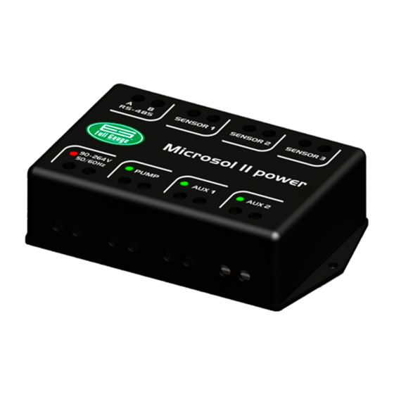
1. DESCRIPTION
Microsol II Power is a differential temperature controller for automation of solar heating systems
that becomes simple the management of the temperature of the water in the thermal reservoirs and
swimming pools, beyond the better use of solar energy .
It acts in the command of the water circulation pump through the differential of temperature between
the solar collectors and the thermal reservoir or swimming pool. It makes use of two solar backing
outputs, that can be electric, gas, diesel or also to program the filtering of the swimming pool. The solar
backing 1 is tied with an schedule that allows the configuration of up to four daily events (for each day of
the week independently) and solar backing 2 can optionally be configured for functioning in set with the
schedule. It has functions that prevent the water freezing and overheating in the tubings and a clock
with internal battery to guarantee its synchronism, even in the energy lack, per many years.
Its main atractions are a versatile switched-mode power supply (90 to 264Vac) and powerful relays
(two 16-Amp and one 30-Amp) that directly commands without the need of magnetic contactors motors
up to 1HP and electrical resistances up to 7500W, saving the users investment in its appliances.
The instrument has serial communication for connection with the SITRAD , Wall-Link e Wall-Fi .
2. APPLICATION
• Solar heating pumped systems
3. TECHNICAL SPECIFICATIONS
- Power supply: 90 ~264Vac ± 10% (50/60Hz) - Also available in 12Vac/dc
- Temperatura de controle: Sensor 1: -50 a 200°C
- Control temperature: Sensor 1: -50 to 200°C / -58 to 392°F
Sensors 2 and 3: -50 to 105°C / -58 to 221°F
- Resolution: 0.1°C between -10 and 100°C and 1°C in the rest of the range
1°F in all range
- Dimensions: 123 x 84 x 34mm
- Operating temperature: 0 to 50°C / 32 to 122°F
- Operating humidity: 10 to 90% RH (without condensation)
- Sensors: S1 - Sensor of the collectors - Metal capsule- Silicone
S2 - Sensor of the Reservoir/Pool - Plastic capsule - PVC
S3 - Sensor for control of solar backings -
- Control outputs: PUMP - Water pump or solenoid - 16(8)A / 250Vac 1HP
AUX1 - solar backing 1 - 16(8)A / 250Vac 1HP
AUX2 - solar backing 2 - 30(15)A/250Vac 2HP
4. ADVANCED SETTINGS
4.1. To access and change the configuration settings
The configuration settings can be accessed and changed through Wall-Fi, Wall-Link or even through
Sitrad software.
4.2.1. Settings parameters
Fun
Description
F01
Differential for turning on the water circulation pump
F02
Differential for turning off the water circulation pump
F03
Minimum temperature at S1 to switch on the pump
F04
Pump switch on delay
F05
Negative differential (S1-S2) to switch on the pump to
dissipate heat
F06
Minimum temperature at S2 to allow activating heat
dissipation
F07
Antifreeze S1 to switch on the pump
F08
Antifreeze hysteresis
F09
Minimum antifreeze time
F10
Overheating temperature S1 to switch off the pump
F11
Overheating hysteresis to switch on the pump
F12
Overheating temperature S2 to switch off the pump
F13
Overheating hysteresis to switch on the pump (S2)
F14
Solar backing 1 operating mode
F15
Solar backing 1 temperature setpoint
F16
Solar backing 1 activation hysteresis
F17
Minimum value for solar backing 1 temperature setpoint
F18
Maximum value for solar backing 1 temperature setpoint
F19
Solar backing 1 manual activation time
F20
Solar backing 2 operating mode
F21
Solar backing 2 temperature setpoint
F22
Solar backing 2 activation hysteresis
F23
Minimum value for solar backing 2 temperature setpoint
F24
Maximum value for solar backing 2 temperature setpoint
F25
Solar backing 2 manual activation time
F26
Cyclic timer on time
F27
Cyclic timer off time
F28
Event schedule linking mode
F29
Minimum S1 temperature alarm
F30
Maximum S1 temperature alarm
F31
S1 temperature indication offset
F32
S2 temperature indication offset
F33
S3 temperature indication offset
F34
RS-485 network address
Microsol II power
DIFFERENTIAL TEMPERATURE
CONTROLLER FOR SOLAR HEATING
WITH TWO SOLAR BACKING
Ver.01
®
®
Plastic
capsule - PVC
CELSIUS
FAHRENHEIT
Min Max Unit
Min Max Unit
Standard
1.0
40.0
°C
8.0
2
72
1.0
40.0
°C
4.0
2
72
-50.0
200
°C
-50.0
-58
392
0
999
sec.
0
0
99
sec.
-40.0
0.0
°C
0.0
-72
0
0.0
105
°C
105
32
221
-18
10.0
°C
3.0
-1
50
0.1
20.0
°C
1.0
1
36
0
999
sec.
0
0
999
sec.
0.0
200
°C
90.0
32
392
0.1
20.0
°C
1
1
36
0.0
105
°C
105
32
221
0.1
20.0
°C
1.0
1
36
0
1
-
0
0
1
-50.0
105
°C
35.0
-58
221
0.1
20.0
°C
1.0
1
36
-50.0
105
°C
-50.0
-58
221
-50.0
105
°C
105
-58
221
0
999
min.
0
0
999
min.
0
5
-
0
0
5
-50.0
105
°C
30.0
-58
221
0.1
20
°C
1.0
1
36
-50.0
105
°C
-50.0
-58
221
-50.0
105
°C
105
-58
221
0
999
min.
0
0
999
min.
1
999
min.
1
1
999
min.
1
999
min.
1
1
999
min.
0
3
-
0
0
3
-50.0
200
°C
-50.0
-58
392
-50.0
200
°C
200
-58
392
-5.0
5.0
°C
0.0
-9
9
-5.0
5.0
°C
0.0
-9
9
-5.0
5.1
°C
0.0
-9
10
1
247
-
1
1
247
4.2.2. Parameters description
F01 - Differential for turning on the water circulation pump
It allows the adjustment of the differential temperature (S1-S2) to activate the water circulation pump. As
the solar collectors receive energy, the temperature in sensor S1 increases. When this temperature is at a
value established as being above the temperature of sensor S2, the pump is turned on and circulates
under the heated water, storing it in the reservoir, for example.
F02 - Differential for turning off the water circulation pump
It allows the adjustment of the differential temperature (S1-S2) to turn off the water circulation pump. With
the pump on, the hot water circulates below and cools upwards. After which time, the temperature
difference between S1 and S2 tends to decrease. When this difference falls to an established level, the
pump is turned off and the water circulation stops.
F03 - Minimum temperature at S1 to switch on the pump
Minimum temperature at sensor 1 to allow switching on the water circulation pump. To deactivate this
®
function just adjust it with the minimum value.
F04 - Pump switch on delay
It allows setting the minimum time the pump must be switched off before being switched on again. It
prevents switching the pump on and off at short intervals, thus increasing pump's service life. It also
defines the delay to switch on the pump after switching on the controller.
F05 - Negative differential (S1-S2) to switch on the pump to dissipate heat
Negative differential (S1-S2) to switch on the water circulation pump. Its allows dissipating heat to reduce
any excess temperature in the water tank. To deactivate this function just adjust it with the maximum value.
F06 - Minimum temperature at S2 to allow activating heat dissipation
Minimum temperature at sensor 2 to allow activating the heat dissipation functions.
F07 - Antifreeze S1 to switch on the pump
It allows setting the temperature for which the collectors start to ice. When the temperature at the collectors
(sensor 1) is too low (e.g. winter nighttime), the pump is switched on at regular intervals to prevent the
water from freezing and damaging the pipes. To deactivate this function just adjust it with the minimum
value.
F08 - Antifreeze hysteresis
Hysteresis for the antifreeze function to switch off the water circulation pump.
F09 - Minimum antifreeze time
Minimum time for which the antifreeze function stays on even if the temperature at sensor 1 returns to the
normal value.
F10 - Overheating temperature S1 to switch off the pump
It allows setting the overheating temperature of the collectors to switch off the water circulation pump.
When the temperature at the collectors (sensor 1) is higher than an adjustable value, the pump is switched
off to prevent the overheated water from circulating through the pipes and damaging them (if PVC pipes
are used).
Standard
F11 - Overheating hysteresis to switch on the pump
°F
14
°F
7
Overheating temperature hysteresis adjustment for sensor 1 to allow switching on the pump again.
°F
-58
F12 -
Overheating temperature S2 to switch off the pump (swiming pool temperature)
0
It allows setting the overheating temperature of the swimming pool to switch off the water circulation
pump to avoid uncomfortable thermal conditions.
°F
0
F13 -
Overheating hysteresis to switch on the pump (S2)
°F
221
Overheating temperature hysteresis adjustment for sensor 2 to allow switching on the pump again.
°F
37
°F
1
F14 -
Solar backing 1 operating mode
0
It allows setting up the operating mode of the solar backing 1 output. The modes are:
°F
194
Solar backing 1 working independently from solar backing 2
0 -
°F
1
1
Solar backing 1 deactivated when solar backing 2 is activated
-
°F
221
°F
1
F15 -
Solar backing 1 temperature setpoint
-
0
Allows setting the activation temperature for solar backing 1.
°F
95
°F
1
F16 - Solar backing 1 activation hysteresis
°F
-58
Hysteresis setting for solar backing 1 activation temperature setpoint.
°F
221
0
F17 - Minimum value for solar backing 1 temperature setpoint
-
0
Lower threshold aimed at preventing an exceedingly low temperature setpoint from being adjusted
°F
86
inadvertently for solar backing 1.
°F
1
°F
-58
F18 - Maximum value for solar backing 1 temperature setpoint
°F
221
Upper threshold aimed at preventing an exceedingly high temperature setpoint from being adjusted
0
inadvertently for solar backing 1.
1
F19 - Solar backing 1 manual activation time
1
-
0
Time for which solar backing 1 stays on when activated manually. After this time solar backing 1 returns
°F
-58
to automatic operation.
°F
392
°F
0
°F
0
°F
0
-
1
Advertisement

Related Manuals for Full Gauge Controls Microsol II power


Summary of Contents for Full Gauge Controls Microsol II power
- Page 1 1. DESCRIPTION 4.2.2. Parameters description Microsol II Power is a differential temperature controller for automation of solar heating systems F01 - Differential for turning on the water circulation pump that becomes simple the management of the temperature of the water in the thermal reservoirs and It allows the adjustment of the differential temperature (S1-S2) to activate the water circulation pump.
- Page 2 A of the instrument connects to Device used to establish the connection Full Gauge Controls’ instruments with the the terminal A of the distribution box, that must be connected with the terminal A of the On1- Start time for the first event ®...
- Page 3 IMPORTANT INTEGRATING MICROSOL II POWER, AND REMOTE INTERFACE According to the chapters of norm IEC 60364: WALL-LINK 1: Install protector against overvoltage on the power supply. 2: Sensor cables and signal cables of the computer may be joined, but not in the same electric conduit through which the electric input and the activation of the loads run.
Need help?
Do you have a question about the Microsol II power and is the answer not in the manual?
Questions and answers