
Related Manuals for ITV SPIKA Series


Summary of Contents for ITV SPIKA Series
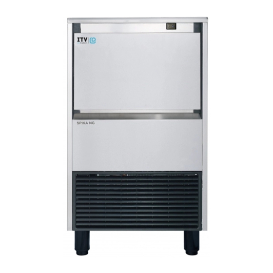
- Page 1 SERVICE MANUAL SPIKA SERIES ICE CUBE MAKERS - UNDERCOUNTER MODELS SPIKA NG 130 SPIKA NG 160 SPIKA NG 230 SPIKA NG 360 ICE CUBE MAKERS - MODULAR MODELS SPIKA MS 500...
- Page 2 SERVICE MANUAL SPIKA SERIES INDEX INTRODUCTION..........................4 1.1.- Warning ............................4 1.2.-Reception of the machine ......................6 INSTALLATION ..........................7 2.1.- Placing of the ice maker ....................... 7 2.2.-Levelling of the ice maker ......................7 2.3.-Installation of modular equipments on top of bins ................8 2.4.-Minimum distance to obstacles ......................
- Page 3 SERVICE MANUAL SPIKA SERIES Refrigeration diagram ........................24 MAINTENANCE AND CLEANING PROCEDURES ................. 25 6.1.- Cleaning water distribution system for under counter models (NG)..........25 6.2.- Cleaning water distribution system for modular models (MS)............28 6.3.- Cleaning the bins (for undercounter models) ................31 6.4.- Cleaning the condenser ......................
- Page 4 SPIKA SERIES 1. INTRODUCTION Thank you for purchasing a ‘Spika Series’ Ice Cube Maker by ITV. You have purchased one of the most reliable ice-making products on the market today. Carefully read the instructions contained in this manual since they provide important information relative to safety during installation, use, and maintenance.
- Page 5 To call to an authorized technical service. Disposal of the ice maker: ITV encourages to follow the regulations of each country regarding eco- friendly disposal of electric and electronic devices such this one. User who is wanting to dispose of this equipment must contact the manufacturer and follow the method to appropriate differentiated collection for the subsequent treatments.
-
Page 6: Reception Of The Machine
SERVICE MANUAL SPIKA SERIES 1.2.-RECEPTION OF THE MACHINE Inspect the outside packing. In case of damages, make the corresponding claim to the carrier. To confirm the existence of damages, unpack the machine in the presence of the carrier and state any damage on the equipment on the reception document or freight document. -
Page 7: Installation
SERVICE MANUAL SPIKA SERIES 2. INSTALLATION 2.1.- PLACING OF THE ICE MAKER This ice maker is not designed for outdoor operation. The icemaker should not be located next to ovens, grills or other high heat producing equipment. The SPIKA machines are designed to operate at room temperature between 10ºC (41ºF) ✓ and 43ºC (109.4ºF). -
Page 8: Installation Of Modular Equipments On Top Of Bins
SERVICE MANUAL SPIKA SERIES 2.3.-INSTALLATION OF MODULAR EQUIPMENTS ON TOP OF BINS Modular ice makers should be installed on top of bins, following the instructions contained in this manual. The resistance and stability of the container-machine/s assembly should be verified as well as the fastening elements. -
Page 9: Water Supply Connection
SERVICE MANUAL SPIKA SERIES The location must allow enough clearance for water drain and electrical connections in the rear of the ice machine. UNDERCOUNTER MODELS MODULAR MODELS 6’’(15cm) Socket Plug 4’’(10c Socket Plug Water inlet Water inlet Water drain drain Bin drain 2.5.- WATER SUPPLY CONNECTION... -
Page 10: Electrical Connection
SERVICE MANUAL SPIKA SERIES It is convenient that the drain hose is 1,18” (30mm) inside diameter and with a minimum gradient of 0.36’’ / ft (3cm/metre), see figure. Incorrect Correct Incorrect 2.5.- ELECTRICAL CONNECTION It is mandatory to ground the equipment. To avoid possible electric shock on individuals or damages to the equipment, the machine should be grounded pursuant local and/or national regulations as the case may be. - Page 11 SERVICE MANUAL SPIKA SERIES AMPS VOLTAGE FUSE TOTAL MODELS FREQUENCY CABLE NEMA PHASE SPIKA NG 130-1 115V / 60Hz / 1F 3AWG16 5-15P SPIKA NG 160-1 115V / 60Hz / 1F 3AWG16 5-15P SPIKA NG 230-1 115V / 60Hz / 1F...
-
Page 12: Prior Checking And Start-Up
SERVICE MANUAL SPIKA SERIES 3. PRIOR CHECKING AND START-UP 3.1.- PRIOR CHECKING a) Is the machine leveled? b) Voltage and frequency are the same as those on the nameplate? c) Are the drains connected and operating? d) Will the ambient temperature and water temperature remain in the following range? - Page 13 SERVICE MANUAL SPIKA SERIES 3.- Verify that the shield moves freely. For modular models verify also the thickness sensor moves freely. And the water tray is in place 4.- Connect the machine to the power supply. 5.- For under counter models: push the switch on the machine front side. For modular models: push the switch found on the back of the machine and then set the ice-wash switch to the position ice.
-
Page 14: Sequence Of Operation Undercounter Models (Ng)
SERVICE MANUAL SPIKA SERIES 4. SEQUENCE OF OPERATION UNDERCOUNTER MODELS (NG) Once you connect the machine there is a time delay of 2 minutes during which the water valve is activated to ensure the water tray is filled. Once the time is up, the compressor starts and the pump which recirculates the water from the water tray to the upper distributor which provides a soft and uniform flow of water over the evaporator cells, in which the water starts freezing. - Page 15 SERVICE MANUAL SPIKA SERIES PCB connections Outputs compressor Water pump Water inlet valve GC Hot gas valve. Inputs Evaporator temperature NTC probe Safety pressure switch MC Curtain switch PCB push button LED signalling Next to each out relay there is an orange led. Signals relay on Next to each input terminal there is an orange led marking input active.
- Page 16 SERVICE MANUAL SPIKA SERIES Safety high pressure switch trip function. ON= automatic reset (minimum stop 30 min.) OFF= manual reset (power OFF-ON) Timeout alarms operation ON = activated OFF = unactivated Software selection. Important: Always OFF for Spika models ICE / WATER TIMER SETTING...
- Page 17 SERVICE MANUAL SPIKA SERIES 4.2.1 SAFETY HIGH PRESSURE SWITCH When the pressure contact (P) trips, instantly, all outputs switch over to off position. When it is closed again, there are two possibilities: - Dip-switch 10 OFF. Manual reset. The machine remains stopped until reset to Initial start-up.
-
Page 18: Sequence Of Operation -Modular Models (Ms)
SERVICE MANUAL SPIKA SERIES 5. SEQUENCE OF OPERATION -MODULAR MODELS (MS) Initial Start-up: The pump and the drain electrovalve are energized during 30 seconds to empty the water tray preventing the scale build-up in water. Then the pump and the drain electrovalve are de-energized, and the water inlet valve is energized filling the water tray until the water level sensor detects the water reaches the appropriate level. - Page 19 SERVICE MANUAL SPIKA SERIES Please note: If at this stage the curtain (MC) is open, the indicated machine status is switched to full storage (full). Production Following outputs are activated: - Compressor (C). - Pump (B). It is activated with delay time t11.
- Page 20 SERVICE MANUAL SPIKA SERIES 30” Open curtain time to activate full storage indication 30” Start-up timing time 180” Harvest maximum time Draining time during operation launching 20” 120’’ Production minimum time 30” Water inlet valve e/w time during production 180”...
- Page 21 SERVICE MANUAL SPIKA SERIES Free Thickness detection sensor Water level in reservoir Connector for staking machines LED signalling By each out relay there is a red led. Signals relay on By each input terminal there is a green leed marking input active.
- Page 22 SERVICE MANUAL SPIKA SERIES In case that a machine stop has been caused by alarm, the resetting is done by disconnecting or by switching over to position 0. If the dip-switch 2 ON, time alarms are not to be followed.
-
Page 23: Machine Stacking
* Signalling: Alternative flashing LE1+LE2 5.9.- MACHINE STACKING It is possible to install two modular machines stacked one above the other with the ITV MS stacking kit (part number 6586). The switchboard must have a connector permitting to connect the boards of both machines with a single cable and also a jumper with the indication: →... - Page 24 SERVICE MANUAL SPIKA SERIES 5 Refrigeration diagram...
-
Page 25: Maintenance And Cleaning Procedures
SERVICE MANUAL SPIKA SERIES 6 MAINTENANCE AND CLEANING PROCEDURES It is the User’s responsibility to keep the ice machine and ice storage bin in a sanitary condition. Ice machines also require occasional cleaning of their water systems with a specifically designed chemical. - Page 26 SERVICE MANUAL SPIKA SERIES c) Remove the back metal lid and the top panel (if it need be to make easier the cleaning operations). d) Remove the auxiliary pipe for drain operations near the pump and empty the water tray.
- Page 27 SERVICE MANUAL SPIKA SERIES h) Disconnect power. i) Remove the auxiliary pipe to drain and purge out the ice machine scale remover and residue. Replace it. j) Mix enough cleaning solution (as in point e) to clean parts and interior food zone surfaces.
- Page 28 SERVICE MANUAL SPIKA SERIES l) Clean all surfaces of the shield with the cleaner solution using a brush (not a wire brush) or cloth. Rinse all areas with water. m) Clean all the interior surfaces of the freezing compartment (including storage bin) with the cleaner solution using a brush or cloth.
- Page 29 SERVICE MANUAL SPIKA SERIES WARNING: Wear rubber gloves and safety goggles when handling Ice Machine Cleaner or Sanitizer. 1) Remove the front panel. 2) Set Ice-wash switch to the OFF position (position 0) after ice falls from the evaporator at the end of a harvest cycle, or set the ice-wash switch to the OFF position and allow the ice to melt off the evaporator.
- Page 30 SERVICE MANUAL SPIKA SERIES MS 500 / 1000 Thickness Curtain sensor Water level sensor Water tray Ice-wash switch Allow the solution to circulate in the water system for 30-40 minutes and then set the ice-wash switch to the OFF position.
-
Page 31: Cleaning The Bins (For Undercounter Models)
SERVICE MANUAL SPIKA SERIES 9) Clean the interior surfaces of the freezing compartment (including walls, plastic parts of the evaporator, distributor...) and the front panel with the cleaner solution using a brush or cloth. 10) Mix a solution of sanitizer using approved sodium hypochlorite food equipment sanitizer to form a solution with 100 t 200 ppm free chlorine yield. -
Page 32: Cleaning The Condenser
SERVICE MANUAL SPIKA SERIES 1) Disconnect the machine, close water faucet and empty storage bin of ice 2) Use the cleaner/water solution to clean all surfaces of the bin. Use a nylon brush or cloth. Then rinse all areas thoroughly with clean water. -
Page 33: External Cleaning Of The Machine
SERVICE MANUAL SPIKA SERIES The water condenser may require cleaning due to scale build-up. The cleaning procedures require special pumps and cleaning solutions. They must be performed by qualified maintenance or service personnel. 6.5.- EXTERNAL CLEANING OF THE MACHINE Clean the area around the ice machine as often as necessary to maintain cleanliness. Sponge any dust and dirt off the outside of the ice machine with mild soap and water. -
Page 34: Technical Specifications
SERVICE MANUAL SPIKA SERIES 7 TECHNICAL SPECIFICATIONS • SPIKA NG UNDER COUNTER • SPIKA MODULAR... - Page 35 SERVICE MANUAL SPIKA SERIES SPIKA NG-MODULAR MACHINE DIMENSIONS PAKAGING DIMENSIONS COOLING (INCH) (INCH) MODELS WIDTH DEPTH HEIGHT WIDTH DEPTH HEIGHT (USA) SPIKA NG 130 21,1 23,4 31,3 24,4 26,0 36,2 SPIKA NG 160 21,1 23,4 31,3 24,4 26,0 36,2 SPIKA NG 230...
-
Page 36: Production Charts
SERVICE MANUAL SPIKA SERIES 7.2.- PRODUCTION CHARTS SPIKA 130 A1F Lb/24h WATER ºF AIR F SPIKA 130 A1H Lb/24h WATER ºF AIR F SPIKA 160 A1F Lb/24h WATER ºF AIR F SPIKA 160 A1H Lb/24h WATER ºF AIR F... - Page 37 SERVICE MANUAL SPIKA SERIES SPIKA 230 A1F Lb/24h WATER ºF AIR F SPIKA 230 A1H Lb/24h WATER ºF AIR F SPIKA 360 A1F Lb/24h WATER ºF AIR F SPIKA MS 500 A1F Lb/24h WATER ºF AIR F...
-
Page 38: Undercounter Models
SERVICE MANUAL SPIKA SERIES 8 USER TROUBLESHOOTING GUIDE 8.1.- UNDERCOUNTER MODELS PROBLEM PROBABLE CAUSE SOLUTION None of the electrical parts The machine is unplugged. Plug in the machine and verify socket power work. Front switch on but pilot is off... -
Page 39: Modular Models
SERVICE MANUAL SPIKA SERIES PROBLEM PROBABLE CAUSE SOLUTION Ice cycle timeout No frozen evaporator Check compressor and refrigeration system NTC probe faulty contact Check probe fitting and insulation Harvest cycle timeout Ice slab not released Faulty hot gas valve Bad leveled unit. check water time too short. - Page 40 SERVICE MANUAL SPIKA SERIES PROBLEM PROBABLE CAUSE SOLUTION Not uniform flow pattern at Dirty or scaled distributor Perform descaling procedure. evaporator Remove and clean distributor (pull from two clips at distributor sides) Low production Dirty condenser Clean (check also incoming water/air temperature)
- Page 41 SERVICE MANUAL SPIKA SERIES 9 WIRING DIAGRAMS 9.1.- SPIKA NG (UNDERCOUNTER MODELS)
- Page 42 SERVICE MANUAL SPIKA SERIES In the next table we have defined the switches configuration to make control of the production time(TF), inlet water time(TD) and production temperature (TC) in all the environments . Number 1-0 means the switch position, ON/OFF.
- Page 43 SERVICE MANUAL SPIKA SERIES 9.2.- SPIKA MS 500 A SINGLE PHASE MODELS DEFAULT DEFAULT DEFAULT (USA) SETTINGS SETTINGS SETTINGS Tª < 70 ºF Tª > 90ºC SPIKA NG 130-A1F 110000001110 010000001110 110000001110 SPIKA NG 130 110000001110 SPIKA NG 130-A1H 110000001110...
- Page 44 SERVICE MANUAL SPIKA SERIES...
Need help?
Do you have a question about the SPIKA Series and is the answer not in the manual?
Questions and answers