Advertisement
Quick Links
Advertisement

Related Manuals for ITV HNG


Summary of Contents for ITV HNG
- Page 1 TECHNICAL INSTALLER´S MANUAL ICE-CUBE MANUFACTURER HNG MODEL...
- Page 2 WARNING The instructions of this manual are exclusively directed to the Technical Assistance Service personnel. The installation of this equipment should be done by the Technical Assistance Service department. IT IS MANDATORY TO GROUND THE EQUIPMENT To avoid possible discharges on individuals or damages to the equipment, the machine should be grounded pursuant local and/or national regulations as the case may be.
-
Page 3: Operation Principle
SPECIALLY THOSE RELATED CLEANING MAINTENANCE OPERATIONS, which should be performed mostly by qualified personnel only. DESCRIPTION The most significant characteristics are: • 18/8 Stainless steel bodywork • Telescopic guides for maintenance • Anti-lock injectors. • Pump without seals. • R134A refrigerants •... - Page 4 SPECIFICATIONS MAIN DIMENSIONS Profundidad Hueco Opening Depth Altura hueco Opening Height...
- Page 5 HNG ICE CUBE MACHINE TECHNICAL DATA MODEL WATER PACKING VOLUME CONSUMPTIO WEIGHT DIMENSIONS WEIGHT (KG) X*Y*Z (KG) L/HOUR (1) 670X685X570 0.27 MODEL REFRIGE REFRIG. PRESSURE IN HIGH PRESSURE TOTAL SECURITY TOTAL RANT LOAD IN LOW INTENS FUSE ABSORBED POWER MINIMUM...
-
Page 6: Installation
ARE A SOURCE OF POTENTIAL HAZARD. INSTALLATION Location zone conditions. The HNG machines are designed to operate at room temperature between 5ºC (41ºF) and 43ºC (109.40ºF). There may be some difficulties in ice- cube removal under the minimum temperatures. Above the maximum temperature, the life of the compressor is shortened and the production is substantially less. - Page 7 Housing dimensions. To install the ice manufacturer in the correct way, it will be necessary that the hole located for such effect in the piece of furniture has the dimensions established in the drawing (560x440x560 mm.). The drainage must be in the position established in the drawing. In the left part of the housing and below the inferior level of the machine.
- Page 8 Toma agua Water connection Toma Eléctrica Power Inlet Salida desagüe Drainage Output Zona libre para paso de la máquina Free space for machine clearance...
- Page 10 IMPORTANT It must be taken into account that an exit must be left for the air that the machines takes through the front louver. It can be a back hole (with an outdoor exit) or a louver on the machine. The water connection, drainage and electrical steps of the equipment are also necessary.
- Page 11 2- Screw the fastening bridge of the machine in the position of the drawing. 3- Screw the fastening flanges of the drainage hoses 4- Place the machine on the support angles of the guides. Adjust the wide before fastening the screws checking that it slides softly along the path.
- Page 12 Water and Drainage The water quality notably affects the quality, hardness and taste of the ice. Have in mind the following considerations: a) WATER IMPURITIES: The big ones are retained by the filters that accompanied each machine. Its cleaning will be more or less periodic in function of the water purity. For the small impurities we recommend the installation of a filter of 5 micron.
- Page 13 d) WATER OF HIGH PURITY: Production can decrease up to a 10%. Connections to the Water Network Use a flexible pipe with the two filter joints supplied with the machine. Pressure should be established between 1 and 5 Kg/cm If pressures overpass such values, install the necessary corrective devices. Leave free the needed length to extract the machine up to the end of the guides.
- Page 14 Voltage and tension are indicated on the nameplate and on the technical specifications of this manual. Variation on voltage above the 10% stated on the nameplate could result on damages or prevent the machine start-up. The line up to the base of the socket shall have a minimum section of 1.5 mm Check that the voltage of the net and the indicated one is the same.
- Page 15 5) Trigger the starting up switch. The display will light with the message Started during 30 seconds, then it will start working with the removal, message in the display dispensing. 6) Verify that there are no vibrations or frictions on the elements. 7) Verify that the shield moves freely.
-
Page 16: Maintenance And Cleaning Instructions
THE EXTRACTION OF THE MACHINE FOR ITS HOUSING MUST ONLY BE MADE BY THE TECHNICAL SERVICE. MAINTENANCE AND CLEANING INSTRUCTIONS CAUTION: INSTRUCT THE USER ABOUT MAINTENANCE PROCEDURES, INDICATING THAT THIS ONE AS WELL AS DAMAGES DUE TO LACK THEREOF, ARE NOT COVERED BY THE WARRANTY. -
Page 17: Maintenance Table
MAINTENANCE TABLE: OPERATION MONTHLY QUARTERLY HALF- ANNUAL BIENNIAL T UNIT YEARLY Air condenser cleaning 0000 0000 **** **** **** 30 minutes Air inlet filter Injector cleaning #### #### **** **** 30 minutes Water circuit cleaning #### #### **** **** 45 minutes Manufacturing Sanitary cleaning ####... - Page 18 Air Condenser-filter 1) Disconnect the machine. 2) Take out the front louver. (pull out the lower clips) 3) Vacuum clean, wash or substitute the filter. 4) Dismantle the lateral lid that covers the condenser 5) If it is necessary clean the louvered area with the help of an aspirator with a brush, non-metallic brush or low-pressure air.
- Page 19 9) CHECK THAT THE INJECTORS ARE PROPERLY LOCATED, THAT THE WATER SPREAD FORMED BY THE INJECTORS ARE UNIFORM AND THAT ALL OF THEM ARE EQUAL. If possible, disassemble, clean and place in the correct position. Ice storage bin cleaning. 1) Disconnect the machine, close the water and empty the ice-cube storage bin. 2) Use a dish cloth with detergent.
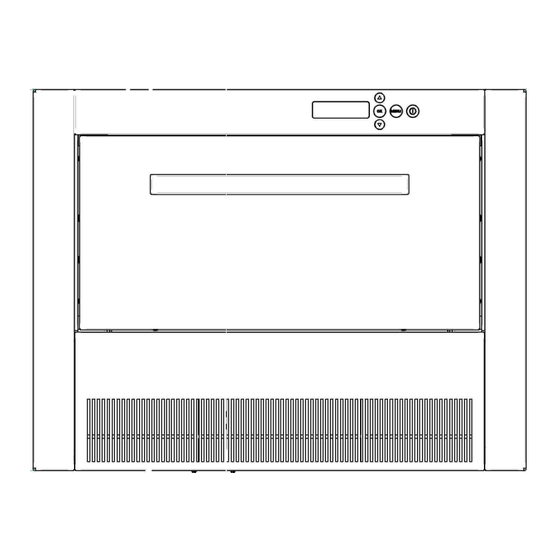
- Page 20 Electronic operation This machine operates by means of the digital electronic controller adapted for ice- cubes in ITV GALA-DELTA manufactures. In the front part of the machine we can see the display and the button panel, by means of which we will access to the different menus, in which we can move to...
- Page 21 User’s menu It can be accessed with the machine turned off and by pressing only once the key “menu”. 1. Time adjustment Main menu It will show the time that the machine has, 1. Adjust time flashing the values that can be changed; with the up/down arrows we will adjust the values and 2.
- Page 22 the maximum time that reaching to the order temperature takes Modify Arrows up/down OK 3. Sp minimum time The minimum time measures the minimum time that reaching to the order temperature takes Modify Arrows up/down OK 4. Manufacturing time The manufacturing time will control the manufacturing time of the machine since it reaches the order temperature up to the removal commencement.
- Page 23 Information Menu You can access the menu any time (with the machine turned on or turned off) by pressing 10” the MENU button. This menu provides machine operation, possible breakdowns, duration of the last processes and temperature information. 1. Room T. / Cycle T. Information Menu It shows the values that are 1.
- Page 24 Inputs Storage bin thermostat I 1234 O 1234 Security Pressure Switch Flooding Free Input Outputs Compressor/Fan Pump Electrovalves Free Output...
- Page 25 TABLE OF ALARMS IN THE DISPLAY Alarm Probable cause Verification Solution Full Storage Thermostat failure In the storage bin the ice Check stock cubes do not touch the thermostat Machine is thermostat rod stopped Cycle probe. Damaged cycle probe Room temperature Replace cycle probe Machine is information menu *****...
- Page 26 Low or no passage of Increase air outlets recommended air outlets or create them if there aren’t any INCIDENCE TABLE Inside the electrical chart is the electronic plate. For incidences, check display codes and corresponding attached instructions. PROBLEM PROBABLE CAUSE SOLUTION 1) The electrical...
- Page 27 20) Everything seems to be working A) The pump lost prime. A) Check the overflow pipe; properly, ensure the water container manufactured in the evaporator. doesn’t leak, the water inlet valve is in good condition and prime the pump. B) Damaged pump. B) Change.
- Page 28 26) The ice cubes are made, A) Water inlet filters are dirty. A) Clean filters. they they aren’t removed. B) Low water pressure. B) Increase pressure. (Sometimes, problem is solved by removing flowmeter from water inlet valve). C) The fan or condensation pressure switch is C) Regulate or change.
- Page 29 47) Empty cubes, with A) Water loss in the container. The pump has A) Eliminate the water irregular and very white lost prime. leak. edges. B) Obstructed injectors. B) Clean injectors. C) The shield slats do not close properly; they C) Adjust the shield slats are blocked and loose water.
Need help?
Do you have a question about the HNG and is the answer not in the manual?
Questions and answers